
Electronic device and data communication control method

a technology of electronic devices and control methods, applied in the field of electronic devices, can solve problems such as the inability to avoid data collision per se, the shortening of the space for forming terminals,

Inactive Publication Date: 2007-05-10
ORION ELECTRIC CO LTD
View PDF8 Cites 4 Cited by
  • Summary
  • Abstract
  • Description
  • Claims
  • Application Information

AI Technical Summary

Benefits of technology

"The present invention aims to provide an electronic device with multiple ICs that can reduce circuit space by reducing data transmission paths for connecting external devices. The invention also aims to prevent misoperation of the device due to data collision with the external device. The invention provides a solution by designing resistors to control signal levels at the host reception connection terminal, which can distinguish between different levels of signals and prevent data collision. This allows for proper data transmission even when there are multiple signals in the system."

Problems solved by technology

The main microcontroller and respective ICs may be connected through individual data transmission paths, but in this case, it is necessary to form terminals in the main microcontroller for connection with the respective ICs and when the number of ICs connected to the main microcontroller increases, there will be a shortage of space for forming the terminals and wider circuit spaces will also be required for forming the respective data transmission paths.
Furthermore, when using the “method of communicating with a plurality of apparatuses using the same signal line”, in the case of the configuration made up of only a “master device” which controls communication and “slave devices”, the master device can control the whole communication to avoid data collision, but when “independent devices” which carry out data transmission without control of the master device are connected to the “same signal line”, it is no longer possible to avoid data collision per se.

Method used


Image

  • Electronic device and data communication control method
  • Electronic device and data communication control method
  • Electronic device and data communication control method

Examples


embodiment 1

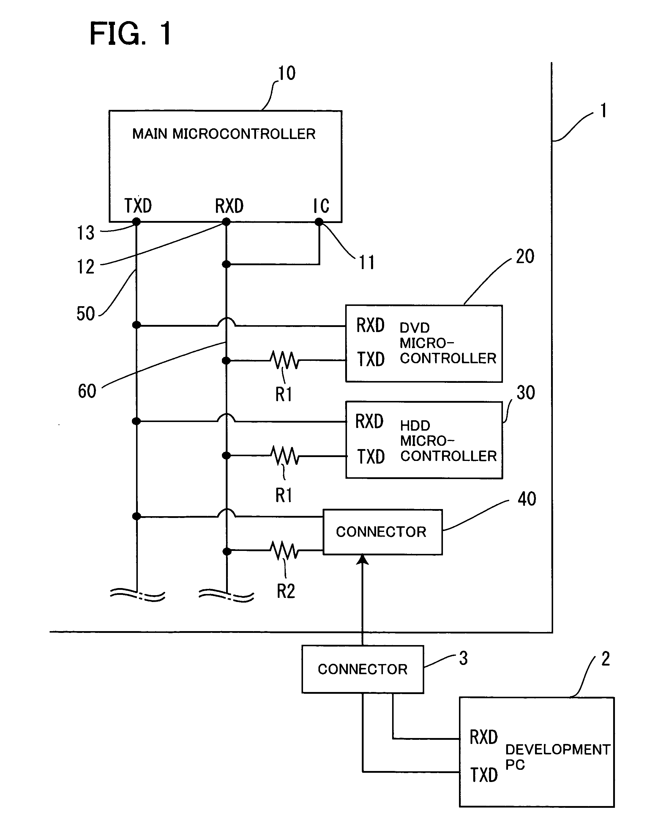
[0040]FIG. 1 is a block diagram schematically showing only parts related to the present invention of a television with a built-in DVD recorder and HDD recorder (hereinafter simply referred to as “DVD / HDD television”).

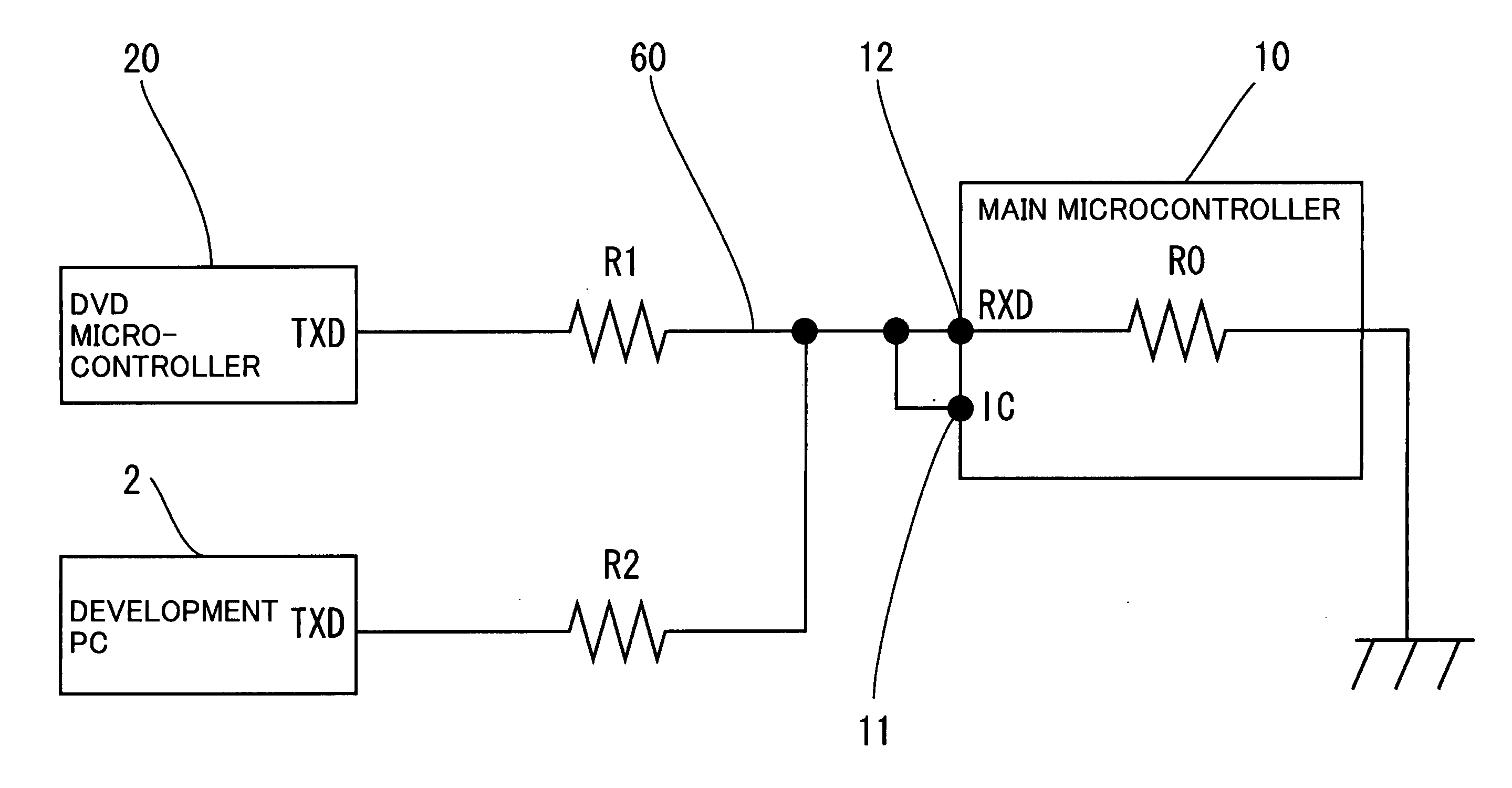
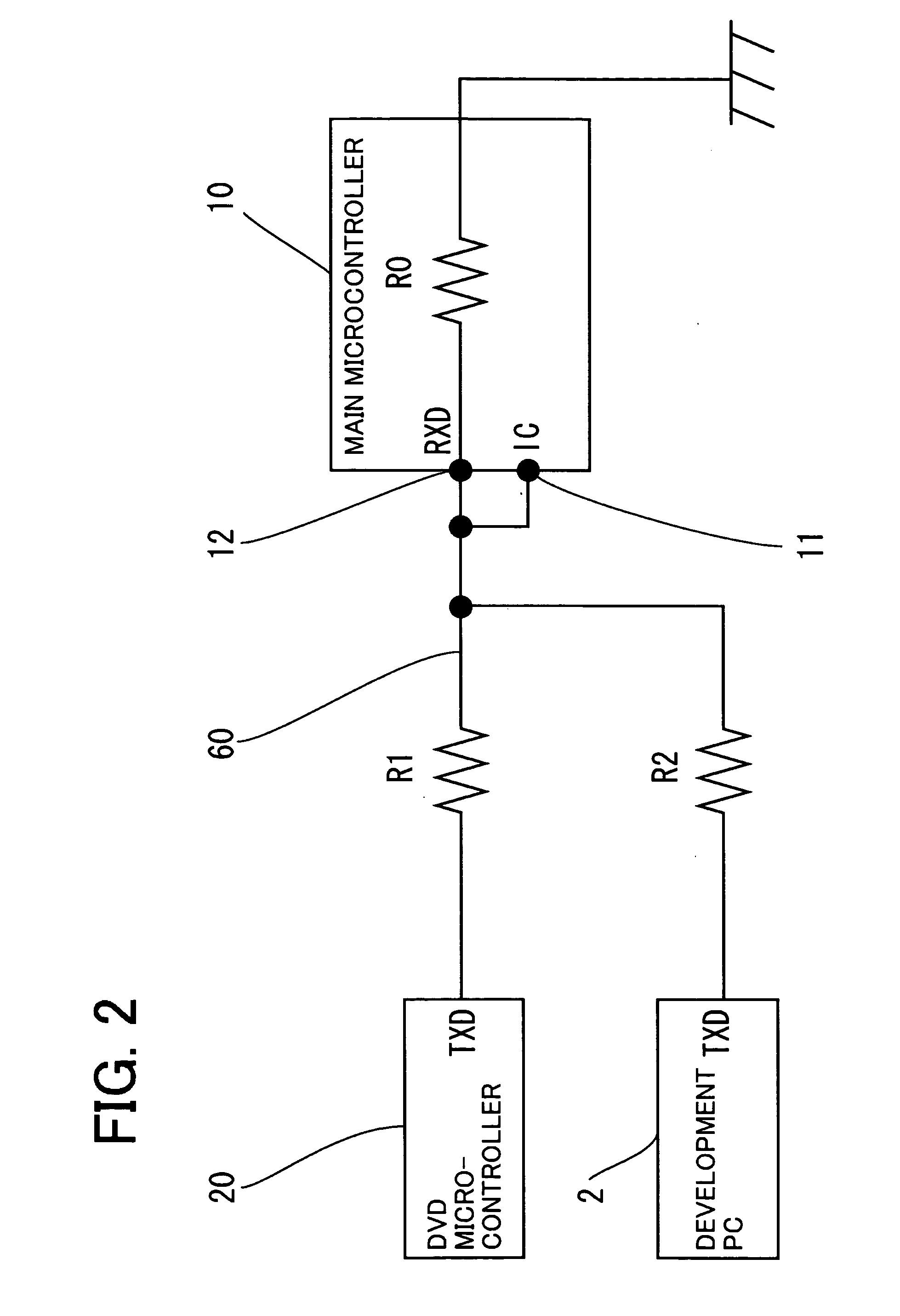
[0041] As shown in FIG. 1, a DVD / HDD television 1 of this embodiment is provided with a plurality of ICs such as a main microcontroller 10 which controls the entire device, a DVD microcontroller 20 which mainly controls a disk (DVD) device, an HDD microcontroller 30 which mainly controls a hard disk (HDD) device. The main microcontroller 10 (host IC), and DVD microcontroller 20 and HDD microcontroller 30 (slave ICs) are connected by sharing a data transmission line 50 and a data reception line 60 and when the data reception line 60 and a voltage monitoring IC terminal 11 provided for the main microcontroller 10 are connected together, the voltage value of the data reception line 60 (RXD terminal 12) is monitored by the main microcontroller 10. Furthermore, a connector ...

embodiment 2

[0055]FIG. 7 is a block diagram illustrating a communication scheme between electronic devices and a method of connection between the electronic devices and FIG. 8 shows differences in output (signal level of transmission data) states between host and independent apparatuses and shows their equivalent circuits.

[0056] As shown in FIG. 7, host apparatus 71 and slave apparatus (device whose communication is controlled by the host apparatus 71) 72 are mutually connected by each apparatus being connected to a communication line 73 through a resistor R4 and a resistor R3. The communication line 73 (one communication line) is used to transmit / receive data between the host apparatus 71 and slave apparatus 72 (that is, half-duplex communication is carried out between the host apparatus 71 and slave apparatus 72). When no data transmission is carried out between the host apparatus 71 and slave apparatus 72, terminals (RXD / TXD terminals) for connection with the communication line are placed i...


PUM


Abstract

The invention provides an electronic device provided with several ICs designed to reduce circuit space by reducing data transmission paths for connecting an external apparatus for developing or debugging software written into the several ICs and prevent misoperation of the device due to data collision on the data transmission path to which the external apparatus is connected. By connecting a connector for connection of a PC to a data reception line and data transmission line which connect a main microcontroller, DVD microcontroller and HDD microcontroller, data transmission paths to connect the PC are reduced and by controlling through voltage control resistors so that the signal level generated at an RXD terminal differs between times of data collision and normal operation and any one of signals of the DVD microcontroller, HDD microcontroller and PC can be read, misoperation in the event of data collision is prevented.

Description

[0001] The present application is based on and claims priority of Japanese patent application No. 2005-303169 filed on Oct. 18, 2005, the entire contents of which are hereby incorporated by reference. BACKGROUND OF THE INVENTION [0002] 1. Field of the Invention [0003] The present invention relates to an electronic device provided with a plurality of ICs, and more particularly, to an electronic device configured so as to connect an external apparatus for developing or debugging software written into the plurality of ICs. [0004] 2. Description of the Related Art [0005] There are many composite type electronic devices having a plurality of different functions. For such a composite type electronic device, ICs for processing their respective functions are often formed modularized and a plurality of ICs is provided in the device. In this case, if the respective ICs operate independently of each other, the device would not function, and therefore an IC which controls the operation of the e...

Claims


Application Information

Patent Timeline
Patent Type & Authority Applications(United States)
IPC IPC(8): G06K19/06
CPCG06F13/4072H04L1/1887
Inventor INOTANI, KAZUNORI
Owner ORION ELECTRIC CO LTD
Learn More