
Punch press with forming dies and operation method for the same

a technology of forming dies and punch presses, which is applied in forging presses, forging/hammering/pressing machines, manufacturing tools, etc., can solve the problems of increasing the size affecting the movement lowering device, and affecting the forming dies. , to achieve the effect of avoiding distorted, facilitating the position switching of the elevating and lowering device, and reducing the moving distance of the elevating

Inactive Publication Date: 2007-05-10
MURATA MASCH LTD
View PDF8 Cites 7 Cited by
  • Summary
  • Abstract
  • Description
  • Claims
  • Application Information

AI Technical Summary

Benefits of technology

[0010] In this configuration, the die supporting member moving device moves the die supporting member to locate one of the forming dies supported on the die supporting member, at the punch position. The forming die located at the punch position is elevated and lowered by the die elevating and lowering driving device. With the elevating and lowering device moved to below the die supporting member by the position switching member, the die elevating and lowering driving device operates to cause the elevating and lowering driving member of the elevating and lowering device to drivingly elevate and lower the elevating and lowering member to raise and lower the forming die. When no forming dies need to be elevated or lowered, the position switching means retreats the elevating and lowering device to the retracting position outside the die supporting member. Since the elevating and lowering device is located at the retracting position outside the die supporting member when no forming dies need to be elevated or lowered, the elevating and lowering device is prevented from interfering with forming dies located close to the forming die fixed at the punch position. This avoids limiting the number and positions of forming dies attached to the die supporting member, and a plurality of forming dies can be freely arranged on the die supporting member depending on operation type or procedure. Further, the elevating and lowering device is retracted to outside the die supporting member except when any forming die is elevated for punching. This prevents slag from adhering to the elevating and lowering device, which can thus always operate appropriately.
[0011] According to the present invention, the die supporting member is a circular or fan-shaped turret that moves rotatably to bring the forming die to the punch position. In this case, the position switching means preferably moves the elevating and lowering device in a direction of a virtual straight line joining the punch position to a rotating center of the turret. When the position of the elevating and lowering device is switched by moving the elevating and lowering device in the direction of the virtual line joining the punch position to the rotating center of the turret, the moving distance of the elevating and lowering device can be minimized to reduce the size of the die elevating and lowering driving device.
[0013] The die supporting member is supported by a bolster from below and be movable in a horizontal direction. In this case, an opening is formed in the bolster so that the elevating and lowering device can enter the opening. When the die supporting member is supported by the bolster from below, the die supporting member is prevented from being distorted during machining. When the opening is formed in the bolster so that the elevating and lowering device can enter the opening, the position of the elevating and lowering device can be switched through the opening. This facilitates the position switching of the elevating and lowering device.
[0014] The punch press with forming dies according to the present invention comprises the die supporting member that supports the plurality of forming dies so that the forming dies can be elevated and lowered, the die elevating and lowering driving device that elevates and lowers the forming dies, and a die supporting member moving device that moves the die supporting member so as to locate one of the forming dies at a punch position. The die elevating and lowering driving device comprises the elevating and lowering member that elevates and lowers the forming die located at the punch position, and the elevating and lowering device composed the elevating and lowering driving member that drivingly elevates and lowers the elevating and lowering member, and further comprises the position switching means for switching the elevating and lowering device between the position below the die supporting member and the retracting position outside the die supporting member. This reduces the limitation on the number and positions of forming dies attached to the die supporting member. The device that elevates and lowers the forming dies can operate appropriately without being affected by slag.
[0015] Where the die supporting member is a circular or fan-shaped turret that moves rotatably to bring the forming die to the punch position, and the position switching means preferably moves the elevating and lowering device in the direction of the virtual straight line joining the position below the die supporting member to the rotating center of the turret, the moving distance of the elevating and lowering device can be minimized to reduce the size of the die elevating and lowering driving device.
[0017] Where the die supporting means is supported by the bolster from below and be movable in the horizontal direction, and the opening is formed in the bolster so that the elevating and lowering device can enter the opening, the die supporting member is prevented from being distorted during machining. This also facilitates the position switching of the elevating and lowering device.

Problems solved by technology

Thus, where a plurality of forming dies are provided in the lower turret in proximity to one another, when one of the forming dies is located at the punch position, the advancing and retreating member may interfere with forming dies located close to the punch position.
However, this disadvantageously increases the size of the elevating and lowering device, and the time required for the forming dies to elevate and lower.
This may hinder the operation of the elevating and lowering device.
This complicates the structure of peripheral portion of the punch position.

Method used


Image

  • Punch press with forming dies and operation method for the same
  • Punch press with forming dies and operation method for the same
  • Punch press with forming dies and operation method for the same

Examples


Embodiment Construction

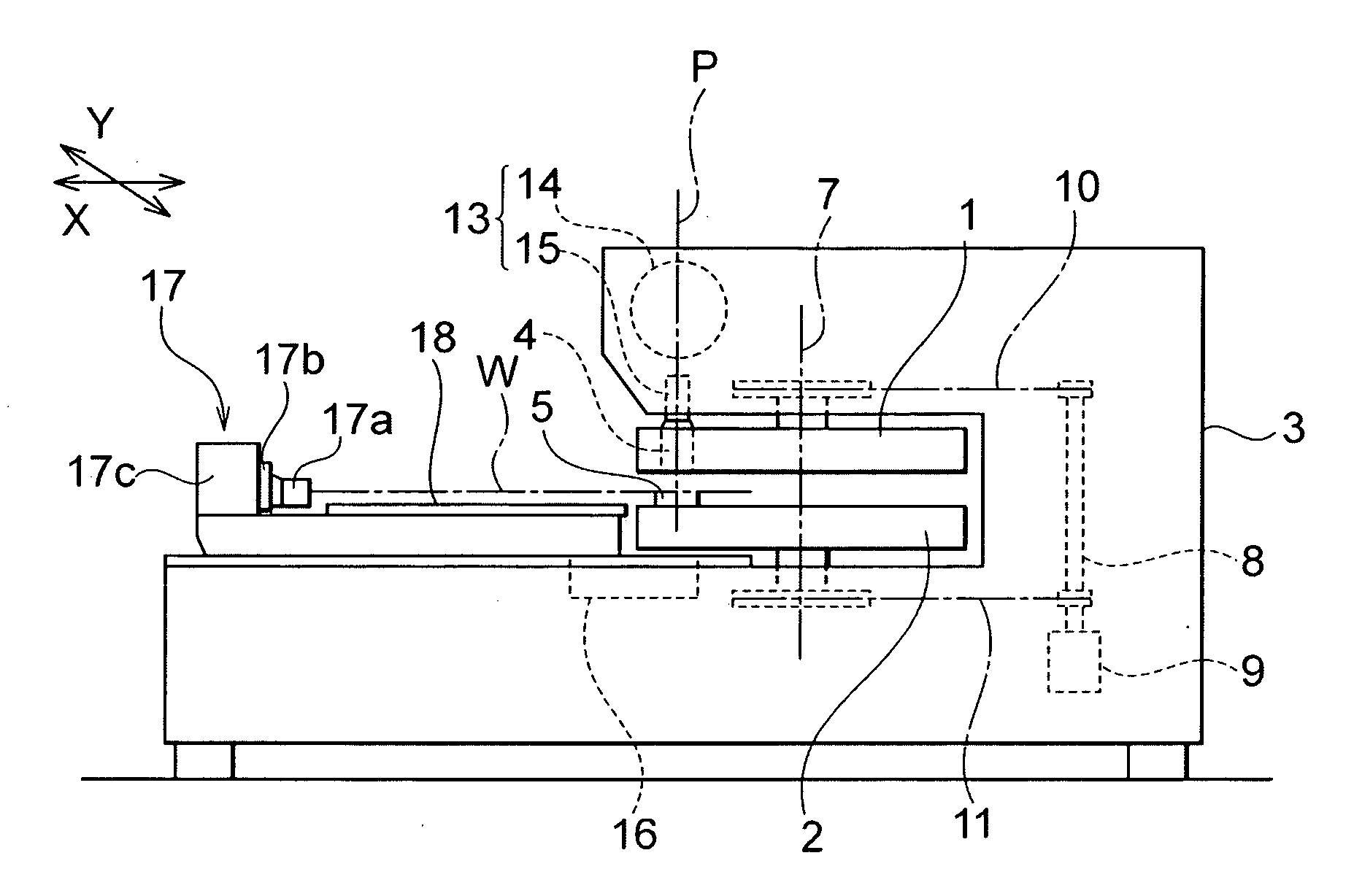
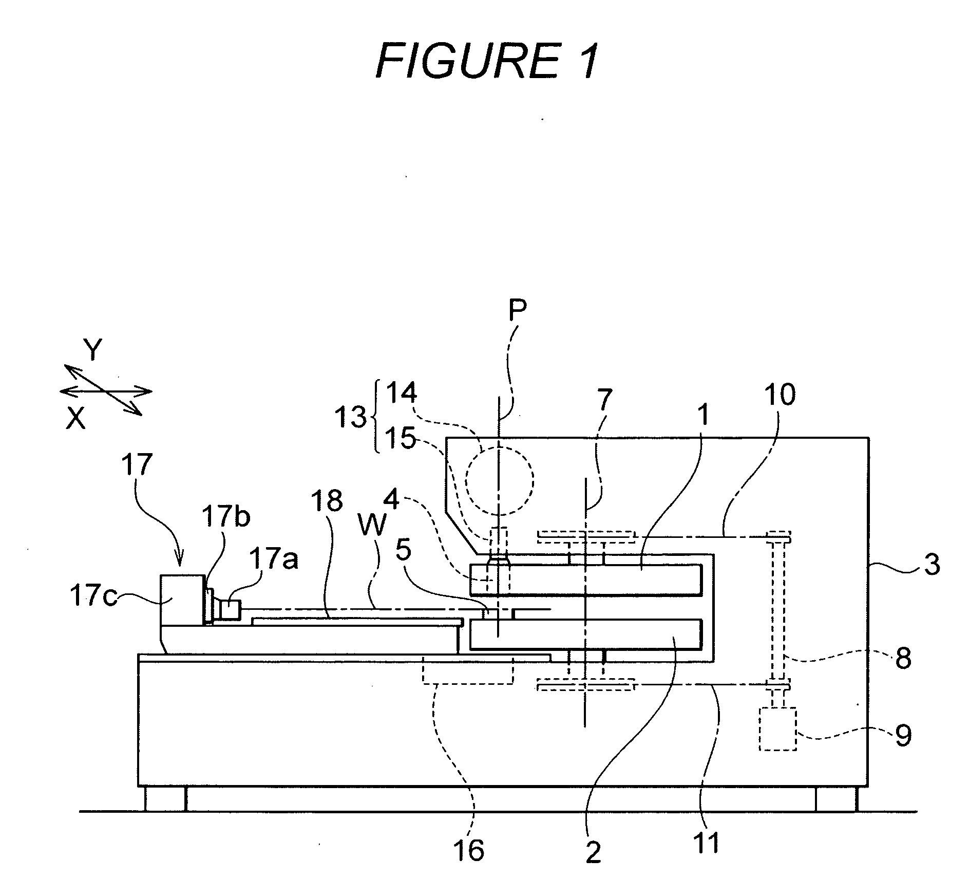
[0033] An embodiment of the present invention will be described with reference to the drawings. This embodiment is obtained by applying the present invention to a turret type punch press shown in FIG. 1. The punch press has an upper turret 1 and a lower turret 2 concentrically arranged in a frame 3; the upper turret 1 is a support member for punch tools and the lower turret 2 is a support member for die tools. An indexing station of the upper turret 1 is provided with various punch tools 4, and an indexing station of the lower turret 2 is provided with various die tools 5.

[0034] Each of the upper turret 1 and lower turret 2 has a circular planar shape and is rotatable around a rotating center axis 7. A turret moving device 8 rotatably moves the upper turret 1 and lower turret 2 to bring any of the punch tools 4 and any of the die tools 5 at a predetermined position P located on circumferences on which the indexing stations are arranged. The turret moving device 8 uses a common moto...


PUM

PropertyMeasurementUnit
heightaaaaaaaaaa
sizeaaaaaaaaaa
circumferenceaaaaaaaaaa

Abstract

The present invention provides a punch press with forming dies which reduces the limitation on the number and positions of forming dies attached to the die supporting member, the punch press enabling a device that elevates and lowers forming dies to operate appropriately without being affected by slag. The punch press with forming dies includes a die supporting member 2 that supports a plurality of forming dies 5 so that the forming dies 5 can be elevated and lowered, a die elevating and lowering driving device 16 that elevates and lowers the forming dies 5, and a die supporting member moving device that moves the die supporting member 2 so as to locate one of the forming dies 5 at a punch position P. The die elevating and lowering driving device 16 includes an elevating and lowering device 30 having an elevating and lowering member 35 that elevates and lowers the forming die 5 located at the punch position P and an elevating and lowering driving member 39 that drivingly elevates and lowers the elevating and lowering member 35, and further includes position switching means 31 for switching the elevating and lowering device 30 between a position B below the die supporting member 2 and a retracting position A outside the die supporting member 2.

Description

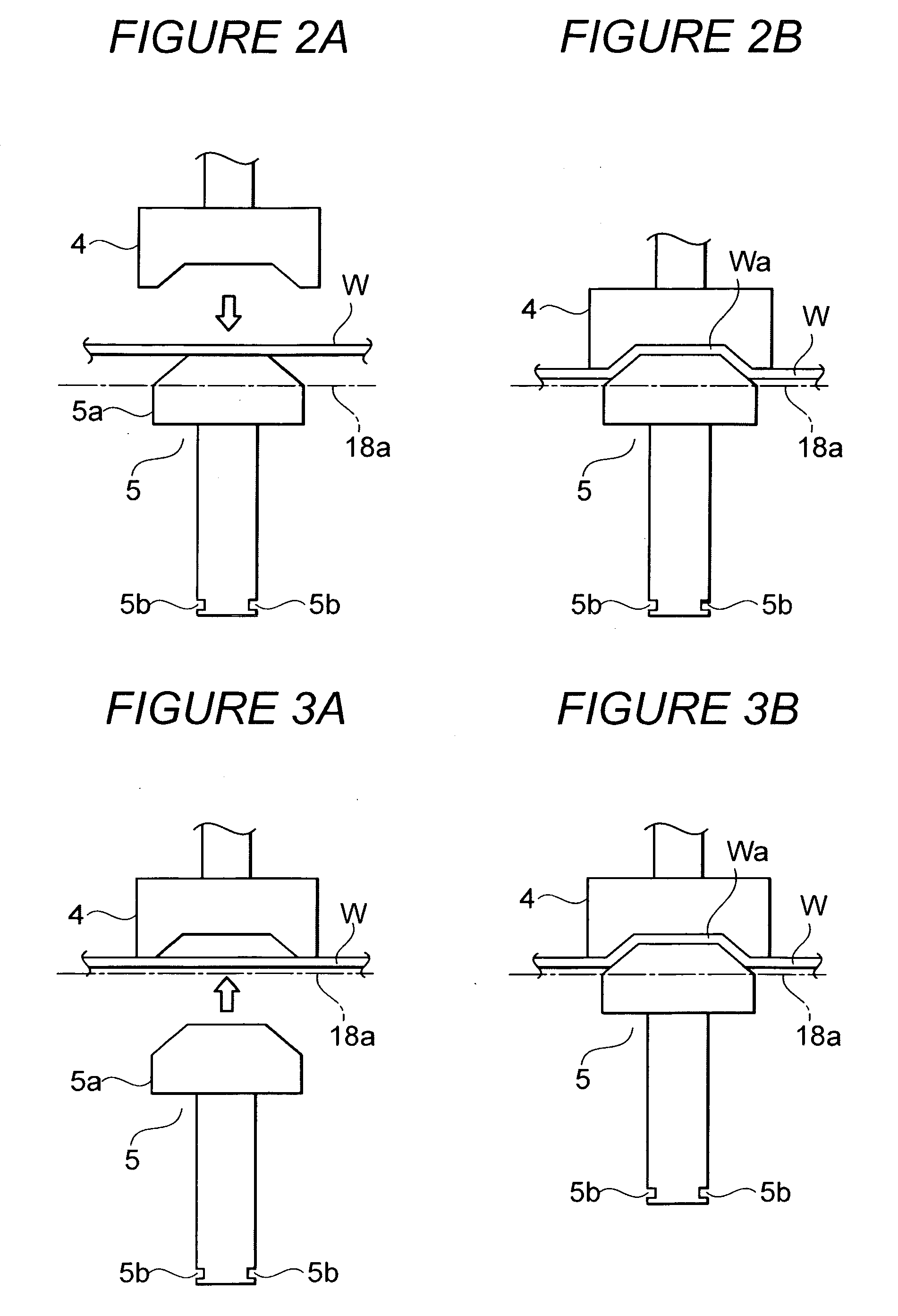
FIELD OF THE INVENTION [0001] The present invention relates to a punch press with forming dies supported on a die supporting member such as a turret, to elevate and lower any of the forming dies for punching, and the present invention also relates to an operation method for a punch press with forming dies. BACKGROUND OF THE INVENTION [0002]FIG. 12 is a diagram showing the general configuration of a turret type punch press. The turret type punch press has an upper turret 1 that circumferentially supports a plurality of punch tools and a lower turret 2 that circumferentially supports a plurality of die tools 5. The upper turret 1 and the lower turret 2 are rotated to locate a desired set of the punch tool 4 and die tool 5 at a predetermined punch position P to punch a workpiece W that is a plate material. [0003] Punching includes piercing and forming. Piercing involves fixing the die tool 5 so that its top surface is flush with a top surface of a workpiece table 18, and under this con...

Claims


Application Information

Patent Timeline
Patent Type & Authority Applications(United States)
IPC IPC(8): B21J7/46
CPCB21D22/08B21D28/12Y10T83/8732Y10T83/175Y10T83/8843
Inventor SAKAMOTO, HIROICHI
Owner MURATA MASCH LTD
Learn More