
Open floor support plate forming equipment with electric control feeding mechanism

A technology of feeding mechanism and forming equipment, which is applied in metal processing equipment, manufacturing tools, feeding devices, etc., can solve the problems of inability to freely adjust the height and number of conveying layers according to needs, inconvenient adjustment operation, and single scope of application. Achieve the effects of low maintenance and replacement costs, simple and convenient adjustment operations, and simple loading and unloading operations

Pending Publication Date: 2020-11-03
江苏来拾科技有限公司
View PDF0 Cites 0 Cited by
  • Summary
  • Abstract
  • Description
  • Claims
  • Application Information

AI Technical Summary

Problems solved by technology

[0005] The technical problem to be solved by the present invention is: in order to solve the problems existing in the above-mentioned background technology, provide an improved opening floor deck forming equipment with an electronically controlled feeding mechanism, and solve the problem that most of the feeding mechanisms currently on the market are fixed in structure, The height and the number of conveying layers cannot be freely adjusted according to the needs, resulting in a very single application range and inconvenient adjustment operations

Method used


Image

  • Open floor support plate forming equipment with electric control feeding mechanism
  • Open floor support plate forming equipment with electric control feeding mechanism
  • Open floor support plate forming equipment with electric control feeding mechanism

Examples


Embodiment

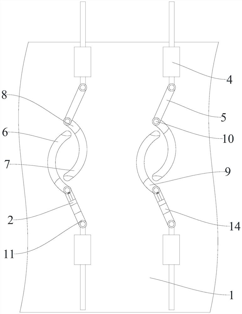
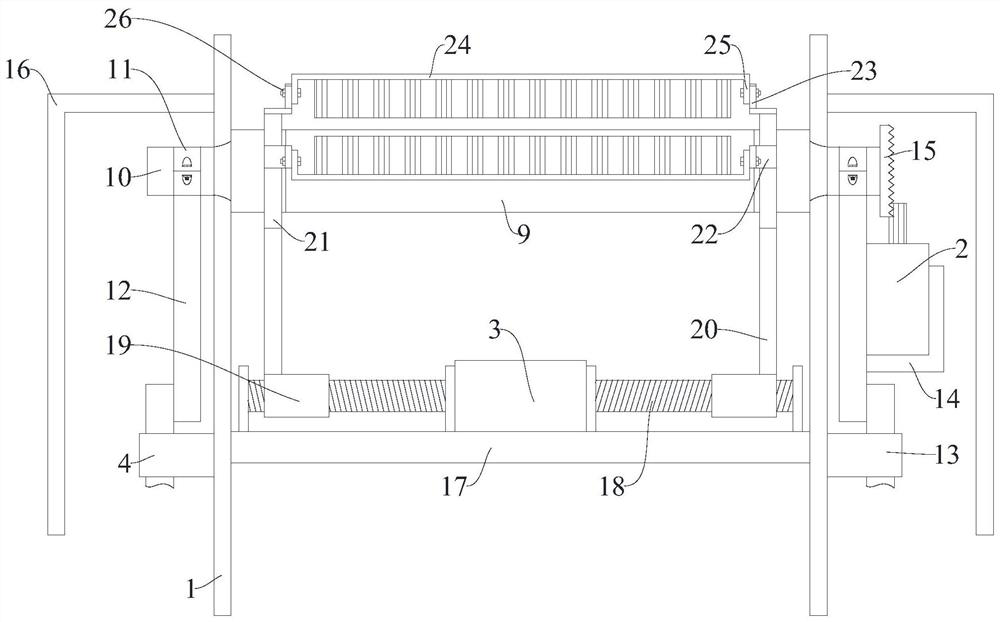
[0025] Example: People control the lifting and lowering of the electronically controlled hydraulic strut 4, and the electronically controlled hydraulic strut 4 drives the lateral link 12 to lift and turn, thereby using the linkage ring 11 to drive the lateral assembly shaft 10 to rise and fall, and the electric power at both ends of the lateral assembly shaft 10 Control hydraulic strut 4 linkage control, synchronous lifting. Because of the arc-shaped dislocation structure, the supporting roller shaft 8 and the driving roller shaft 9 can be lifted and lowered in a dislocation, and the minimum space layout is convenient for the two to switch positions.

[0026] At the same time, the driving motor 2 drives the lateral assembly shaft 10 to rotate through rotation.

[0027] Further, in order to improve the guiding stability and facilitate the installation of the drive mechanism, the outer side of the molding machine body 1 is bolted with a side guide tube 13 for improving the stability ...


PUM


Abstract

The invention relates to the technical field of building board machining and production, in particular to open floor support plate forming equipment with an electric control feeding mechanism. The forming equipment comprises a forming machine body used for producing and machining open floor support plates, driving motors used for controlling the forming machine body to operate, a transverse adjusting motor, electric control hydraulic supporting rods and numerical control machining modules used for controlling the forming machine body to operate. According to the open floor support plate forming equipment with the electric control feeding mechanism, arc-shaped left side adjusting openings used for installing supporting roller shafts and arc-shaped right side adjusting openings used for installing transmission roller shafts are formed in the outer wall, and lateral connecting rods at the lower ends of linkage rings are used for being movably connected with lifting rods at the upper endsof the electric control hydraulic supporting rods so that the height and the position of the supporting roller shafts and the transmission roller shafts can be freely adjusted according to needs, andthe height and the number of layers of the feeding mechanism are freely changed according to needs by the forming equipment, so that the forming equipment is wider in application range, and easy and convenient in adjustment operation.

Description

Technical field [0001] The invention relates to the technical field of processing and production of building boards, in particular to an open floor deck forming equipment with an electric control feeding mechanism. Background technique [0002] The pressed steel plate that supports the floor concrete is called the pressed steel plate, also called the floor deck. [0003] Floor decks are widely used in power plants, power equipment companies, automobile exhibition halls, steel structure factories, cement warehouses, steel structure offices, airport terminals, railway stations, stadiums, concert halls, grand theaters, large supermarkets, logistics centers, and the Olympics Steel structure buildings such as stadiums and stadiums. To meet the requirements of rapid construction of the main steel structure, it can provide a firm working platform in a short time, and can use multiple floors to lay profiled steel plates and layered concrete slabs. [0004] The floor deck forming machine on...

Claims


Application Information

Patent Timeline
Patent Type & Authority Applications(China)
IPC IPC(8): B21D43/00B21D22/02
CPCB21D43/00B21D22/02
Inventor 李国团
Owner 江苏来拾科技有限公司
Learn More