Dual sine-wave time stamp method and apparatus

a time stamp and sine wave technology, applied in multiplex communication, instruments, horology, etc., can solve the problems of methods that suffer from inaccuracy and require calibration, and capacitive timing methods which use ramp waveforms are particularly susceptible to noise, and achieve high resolution

Active Publication Date: 2007-05-03
TERADYNE
View PDF25 Cites 10 Cited by
  • Summary
  • Abstract
  • Description
  • Claims
  • Application Information

AI Technical Summary

Problems solved by technology

However, this method suffers from some inaccuracy and requires calibration because the discharge rate of capacitors is generally non-linear and can differ significantly among capacitors.
Timing methods such as capacitive timing methods which use ramp waveforms are particularly susceptible to noise because ramp waveforms occupy a wide frequency band.
Increasing the slope of a ramp waveform can reduce noise but at the cost of higher current which increases power consumption and emissions, among other disadvantages.

Method used


Image

  • Dual sine-wave time stamp method and apparatus
  • Dual sine-wave time stamp method and apparatus
  • Dual sine-wave time stamp method and apparatus

Examples


Embodiment Construction

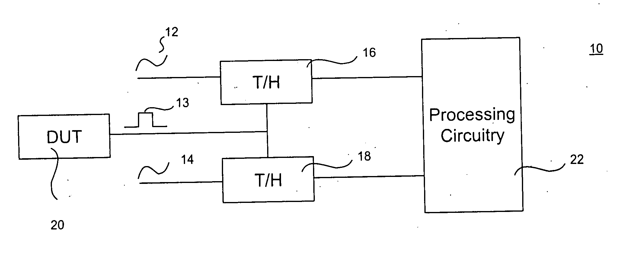
[0020] An apparatus according to an illustrative embodiment of the invention for identifying the time of an event in a signal with precision that is not limited by the period of a timing signal is described generally with reference to FIG. 1. It should be understood by persons having ordinary skill in the art that the amplitude of a periodic timing signal, such as a sine wave, for example, is a function of phase angle and a function of time, but the inverse is not true. For example, in a periodic timing signal, neither time nor phase angle are a function of amplitude, i.e., they do not have a 1:1 signal space to time relationship because there are two times and phase angles in each period of a periodic signal which correspond to particular amplitude. Accordingly, it is necessary to acquire more than just one timing signal amplitude in order to determine the phase angle of the timing signal. Various illustrative embodiments of the present invention may achieve a 1:1 signal space to t...


PUM


Abstract

A time of an event can be determined by acquiring an amplitude, at the time of the event, of at least two periodic timing signals that are out of phase with each other. The time of the event within a cycle of at least one of the timing signals can be determined as a function of the amplitudes of the timing signals. The phase angle and complex coordinates of at least one of the timing signals can be determined as a function of the amplitudes. The time of the event within a cycle of a timing signal can be determined as a function of the phase angle or complex coordinates of the timing signal at the time of the event.

Description

FIELD OF THE INVENTION [0001] The present invention relates generally to the field of signal timing measurement. BACKGROUND OF THE INVENTION [0002] Testing of data communication devices and other electronic devices often involves waveform timing analysis in which it is necessary to record the exact time that an event in a waveform occurs. As the volume of data being transmitted through devices has been increasing, the speed of the signal waveforms that must be analyzed has also been increasing. [0003] Typical time stamping circuitry counts the number of pulses received from a reference clock before an event in a waveform under test is detected. The time resolution of the counter method that is used in this type of time stamping circuitry is limited to the period of the reference clock and the maximum counting speed of the counter circuitry. [0004] It has been known to extend time stamp resolution to less than one period of a reference clock by charging and discharging a capacitor wi...

Claims


Application Information

Patent Timeline
Patent Type & Authority Applications(United States)
IPC IPC(8): G01R35/00G01R13/00H04L9/00H04J3/06
CPCG04F10/00G04F10/06
Inventor XU, FANG
Owner TERADYNE
Why Eureka
Try Eureka