Surgical variable-angle illuminator

a wide-angle illuminator and variable-angle technology, applied in the field of surgical instruments, can solve the problems of glare of available wide-angle illuminators, sub-optimal light refraction, and matching of the light refracting index of vitreous eye fluid, and achieve the effect of reducing angular spread and high efficiency

Active Publication Date: 2007-05-03
ALCON INC
View PDF20 Cites 16 Cited by
  • Summary
  • Abstract
  • Description
  • Claims
  • Application Information

AI Technical Summary

Benefits of technology

[0010] In the CPC cone embodiment, the distal end of the optical fiber is terminated in a CPC-cone shape that angularly spreads the light out to a high off-axis angle and emits the light out of the distal end of the cannula with high efficiency. Almost all of the light beam escapes the optical fiber and CPC-cone through the planar distal end face. A male CPC-cone is separated from a truncated female CPC-cone by a small air gap. When the male and female CPC-cones are pulled together to make optical contact, the light from the male CPC-cone element is freely transmitted into the female CPC-cone element, and the resultant light is emitted over a greatly reduced angular spread.

Problems solved by technology

One disadvantage exhibited by some prior art wide-angle illuminators for ophthalmic surgery is matching of the light refracting index of the vitreous eye fluid to that of the light refracting surface of the lens of the illuminator that comes in contact with the vitreous eye fluid.
Contact of the vitreous eye fluid with the light refracting surface of the light spreading lens of such prior art systems results in sub-optimal light refraction due to index switching caused by the vitreous eye fluid.
Another disadvantage of currently available wide-angle illuminators is glare.
Glare is unwanted stray radiation that provides no useful illumination, and either distracts an observer or obscures an object under observation.
A further disadvantage of prior art wide-angle illuminators is that they do not provide for varying the illumination angle (angular spread) of the light source to adjust illumination for different conditions within the surgical field in real time.

Method used


Image

  • Surgical variable-angle illuminator
  • Surgical variable-angle illuminator
  • Surgical variable-angle illuminator

Examples


Embodiment Construction

[0021] Preferred embodiments of the present invention are illustrated in the FIGURES, like numerals being used to refer to like and corresponding parts of the various drawings.

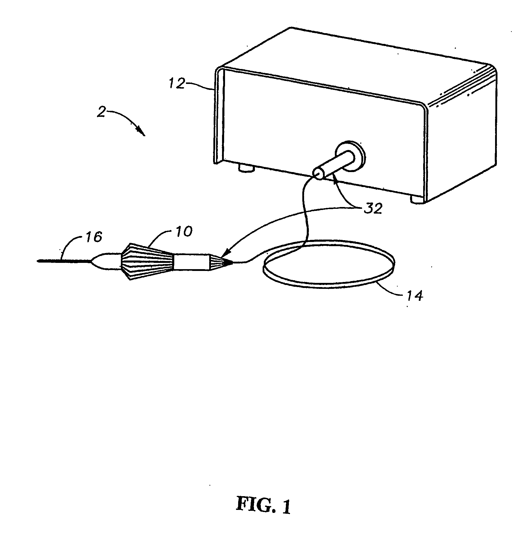
[0022] The various embodiments of the present invention provide for a small gauge (e.g., 19, 20, or 25 gauge) optical fiber based endo-illuminator device for use in surgical procedures, such as in vitreo-retinal / posterior segment surgery. Embodiments of this invention can comprise a handpiece, such as the Alcon-Grieshaber Revolution-DSP™ handpiece sold by Alcon Laboratories, Inc., Fort Worth, Tex., connected to a small gauge cannula (e.g., 19, 20, or 25 gauge). The inner dimension of the cannula can be used to house one, or a plurality of, optical fibers and / or a diffusive optical element in accordance with the teachings of this invention. Embodiments of the wide-angle illuminator can be configured for use in the general field of ophthalmic surgery. However, it is contemplated and it will be realized by those...


PUM


Abstract

A variable-angle, wide-angle illuminator is disclosed, one embodiment being a small-gauge, variable-angle illumination surgical system comprising: a light source for providing a light beam; an optical cable, optically coupled to the light source for receiving and transmitting the light beam; a handpiece, operably coupled to the optical cable; an optical fiber, operably coupled to the handpiece, wherein the optical fiber is optically coupled to the optical cable to receive and transmit the light beam; an optical assembly, optically coupled to a distal end of the optical fiber, for receiving the light beam and providing the light beam to illuminate a surgical field; and a cannula, operably coupled to the handpiece and optical assembly, for housing and directing the optical assembly to illuminate a selected area, such as a surgical site. The optical assembly can comprise, for example, a fiber/polymer-dispersed-liquid-crystal (“PDLC”) diffuser optically coupled to an optical needle or a nested compound parabolic concentrator (“CPC”) cone. In the PDLC diffuser/needle embodiment, the fiber can be a standard endo-illuminator optical fiber with 0.50 NA or similar value. The light beam from the light source is emitted from the distal end of the optical fiber and provided to the PDLC diffuser for further transmission. The degree of diffusion of the light beam at the PDLC diffuser can be electrically controlled and can be varied from no diffusion to very high degree of diffusion. After passing through the PDLC diffuser, the light beam is provided to a needle or fiber, such as a glass needle or fiber, that transmits the light beam to the surgical site in the eye.

Description

CROSS-REFERENCE TO RELATED APPLICATIONS [0001] This application claims priority under 35 U.S.C. §119 to U.S. Provisional Patent Application No. 60 / 731,942, filed Oct. 31, 2005, the entire contents of which are incorporated herein by reference.TECHNICAL FIELD OF THE INVENTION [0002] The present invention relates generally to surgical instrumentation. In particular, the present invention relates to surgical instruments for illuminating an area during eye surgery. Even more particularly, the present invention relates to a variable-angle, small gauge, wide-angle illuminator for illumination of a surgical field. BACKGROUND OF THE INVENTION [0003] In ophthalmic surgery, and in particular in vitreo-retinal surgery, it is desirable to use a wide-angle surgical microscope system to view as large a portion of the retina as possible. Wide-angle objective lenses for such microscopic systems exist, but they require a wider illumination field than that provided by the cone of illumination of a ty...

Claims


Application Information

Patent Timeline
Patent Type & Authority Applications(United States)
IPC IPC(8): A61B18/18
CPCA61F9/007A61B2019/5206A61B2090/306
Inventor SMITH, RONALD T.
Owner ALCON INC
Why Eureka
Try Eureka