
Integral solid-state luminaire with dual light paths and coaxial optics

a coaxial optics and integrated technology, applied in lighting and heating equipment, instruments, lighting support devices, etc., can solve the problems of not teaching the use of solid-state light sources or coaxial optics, and achieve the effects of reducing the user's freedom of movement, reducing the weight of the headlight, and reducing the beam intensity and uniformity

Inactive Publication Date: 2007-05-03
WELCH ALLYN INC
View PDF5 Cites 33 Cited by
  • Summary
  • Abstract
  • Description
  • Claims
  • Application Information

AI Technical Summary

Benefits of technology

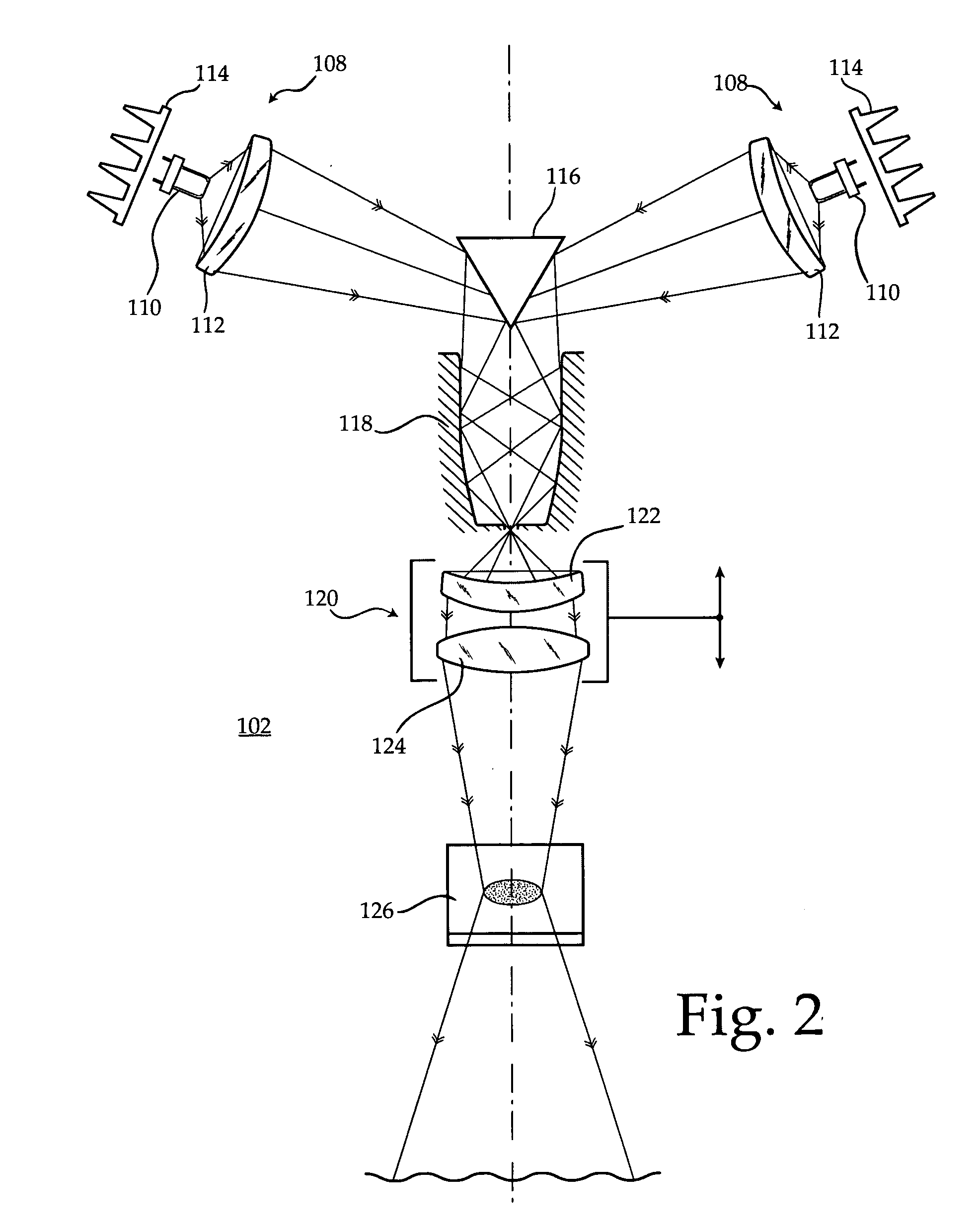
[0010] An advantage of the present invention is that the multiple solid-state light sources are projected through a lightweight and versatile coaxial optics system and therefore create an output illumination beam that behaves as though it was produced by a single source. The invention requires only minimal adjustment of the output beam such as to control the size of the illumination spot. Further, the invention provides a sufficiently intense and uniform beam without the need for a remote high-intensity light source thus lacking a fiber optic cable that adds weight to the headlight and restricts the user's freedom of motion. Even further, the invention provides an optional aperture wheel that gives the user flexibility in the special distortion, intensity, and shape of the projected spot.
is that the multiple solid-state light sources are projected through a lightweight and versatile coaxial optics system and therefore create an output illumination beam that behaves as though it was produced by a single source. The invention requires only minimal adjustment of the output beam such as to control the size of the illumination spot. Further, the invention provides a sufficiently intense and uniform beam without the need for a remote high-intensity light source thus lacking a fiber optic cable that adds weight to the headlight and restricts the user's freedom of motion. Even further, the invention provides an optional aperture wheel that gives the user flexibility in the special distortion, intensity, and shape of the projected spot.

Problems solved by technology

However, the challenge is to deliver a sufficiently intense beam of light along an axis that lies in the same plane with the user's viewing paths.
Kim does not teach the use of solid-state light sources or the use of coaxial optics.
The headlamp taught by Gupta requires the user to adjust the separate lamps to converge on the work surface and does not teach coaxial optics.

Method used


Image

  • Integral solid-state luminaire with dual light paths and coaxial optics
  • Integral solid-state luminaire with dual light paths and coaxial optics
  • Integral solid-state luminaire with dual light paths and coaxial optics

Examples


Embodiment Construction

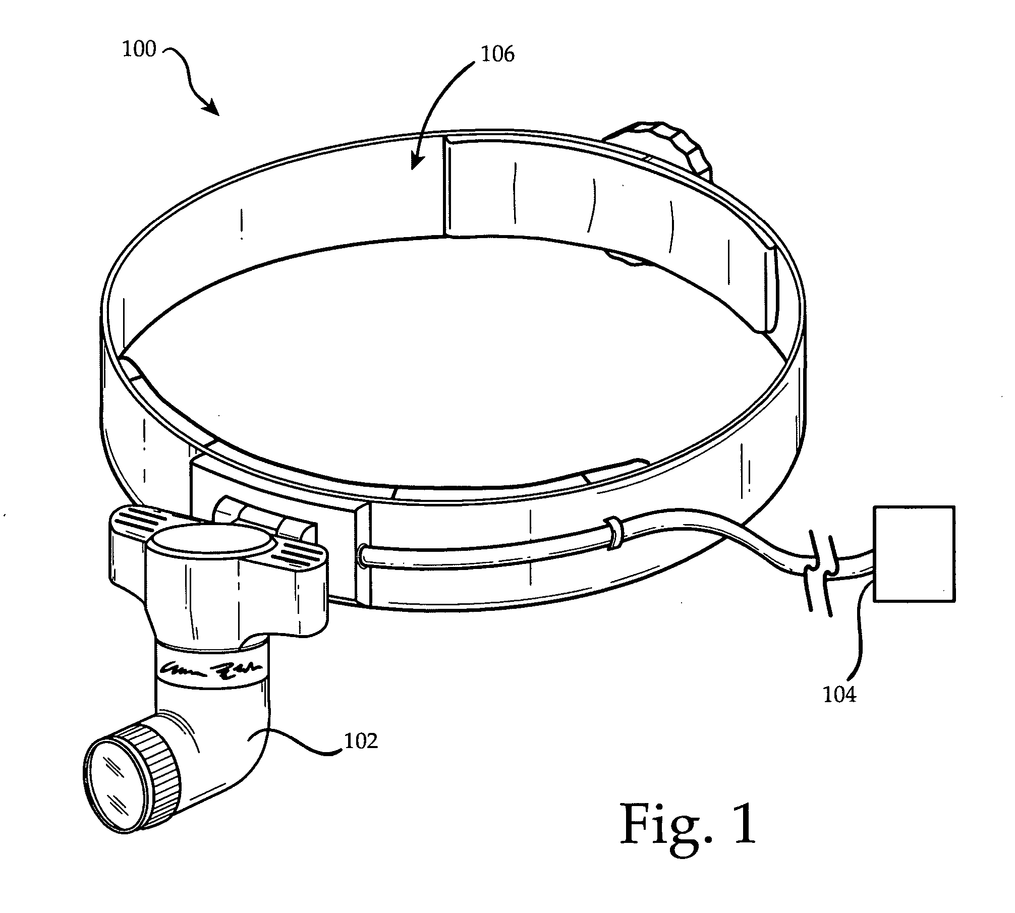
[0016] The luminaire of the present invention is shown in FIG. 1. The apparatus 100 includes a luminaire housing 102, a battery pack 104, and an headband 106. The headband 106 may take any of a number of forms that engage the user's head and provide a stable support for the luminaire housing 102.

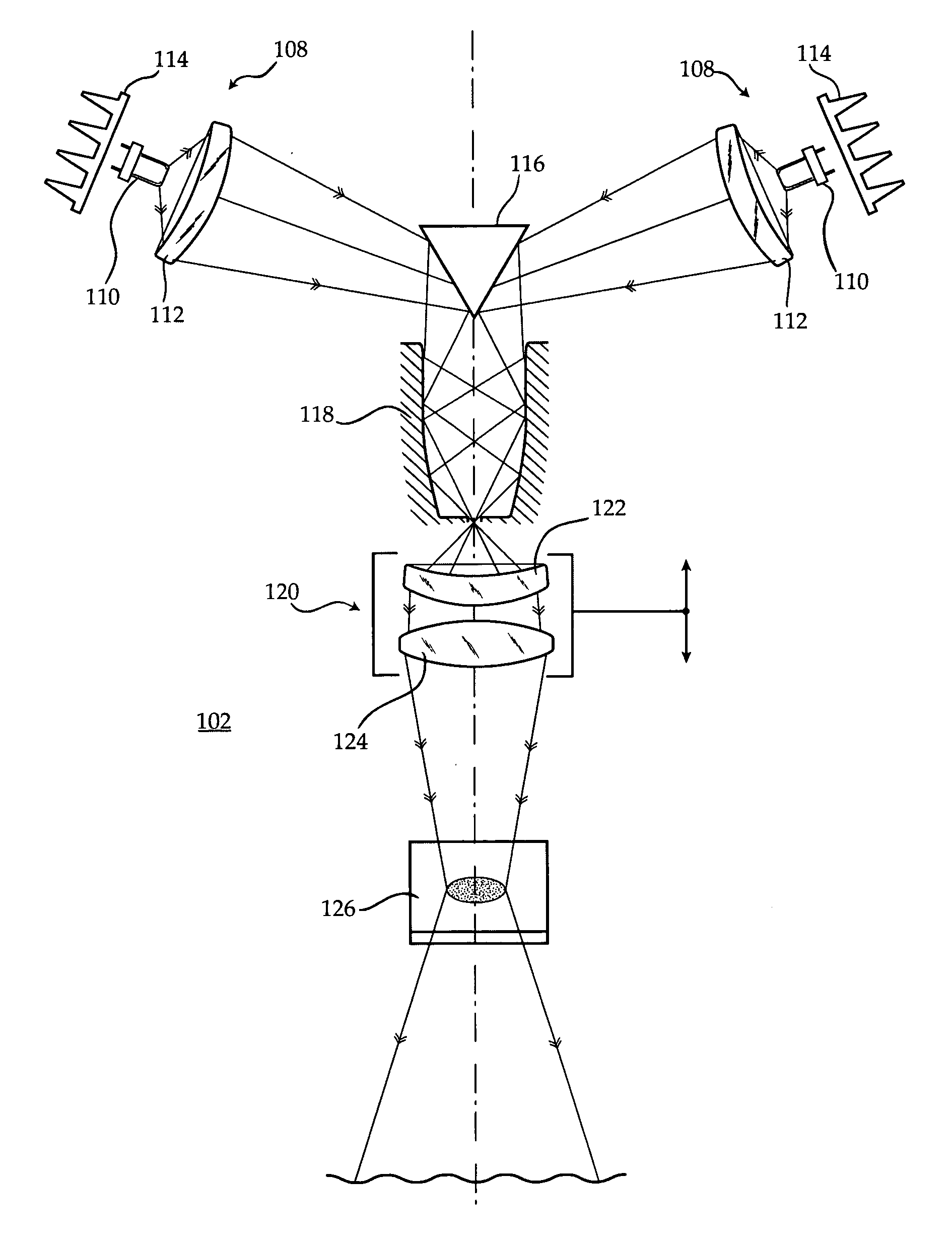
[0017] The luminaire housing 102 encloses the solid state light sources and the optics shown schematically in FIG. 2. A pair of opposing solid-state light sources 108 are provided on opposite sides of the housing 102 to distribute the weight of the housing 102 and allow improved heat dissipation. Each of the light sources 108 includes a white LED 110 such as a 5 watt LED sold under the trademark Luxeon, an aspheric condensing lens 112, and a distributed heat sink 114. The condensing lens 112 may be a Fresnel lens to reduce the size and weight of the lens. A light collimator such as those made by the Fraen Corporation may be used to direct the majority of the light from the LED 110 into the ...


PUM


Abstract

The invention includes a light and compact illuminator that can be powered from a portable and rechargeable battery. The illuminator includes two independent solid-state light sources and optics to converge the beams into a single high-intensity output beam. The components are enclosed in a lightweight, head-mounted housing.

Description

FIELD OF THE INVENTION [0001] This invention relates to a surgical headlight with an integral light source. BACKGROUND OF THE INVENTION [0002] Surgeons and other personnel who work in the medical field are often required to illuminate a portion of a patient during surgical procedures. The nature of the surgeon's duties during such procedures requires that they maintain a degree of free use of their hands. These requirements are generally satisfied by illumination assemblies known in the art as surgical headlights. Surgical headlights are mounted on the surgeon's head, and serve to illuminate the patient. The surgical headlight is an luminaire held on the surgeon's head with a headband, and having a high intensity light source. Generally, the high intensity light source is connected to the headband by a fiber-optic cable that serves to carry the light from the fiber optic light source to a luminaire. [0003] LED technology is quickly emerging as a forerunner in solid-state illuminatio...

Claims


Application Information

Patent Timeline
IPC IPC(8): F21V5/00F21S4/00
CPCF21L4/02F21L4/04F21V13/14F21V21/084F21W2131/20F21Y2101/02G02B7/002G02B27/0955G02B27/143G02B19/0066G02B19/0028F21Y2115/10
Inventor GOLDFAIN, ERVIN
Owner WELCH ALLYN INC
Learn More