Heat dissipation device
a heat dissipation device and heat dissipation technology, applied in the direction of cooling/ventilation/heating modification, semiconductor device details, semiconductor/solid-state device details, etc., can solve the problems of affecting the performance and reliability of the computer, requiring an increase in heat dissipation, and the enhanced functionality and complexity of the newer microprocessors. , to achieve the effect of promoting heat dissipation, reducing airflow loss, and simple structur
- Summary
- Abstract
- Description
- Claims
- Application Information
AI Technical Summary
Benefits of technology
Problems solved by technology
Method used
Image
Examples
first embodiment
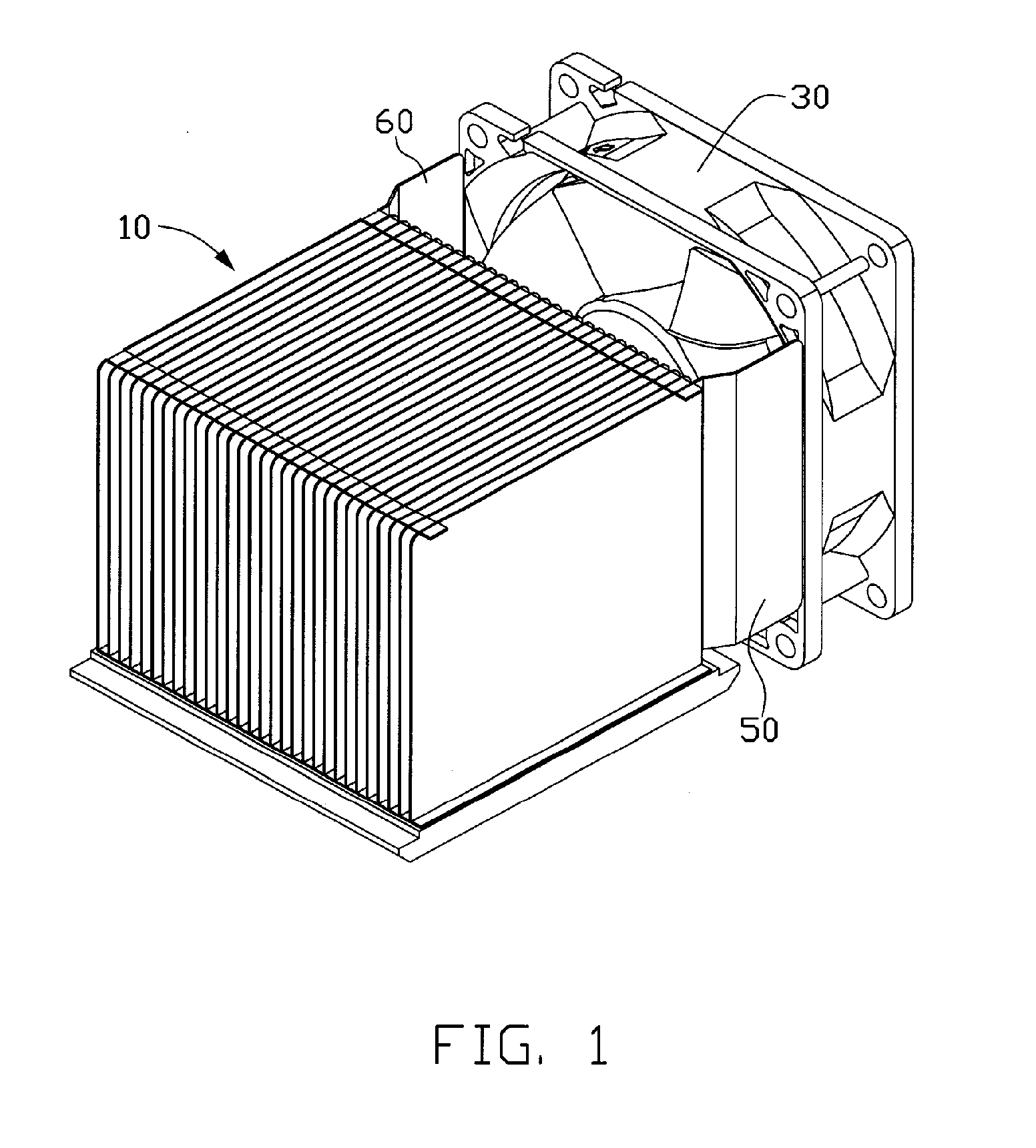
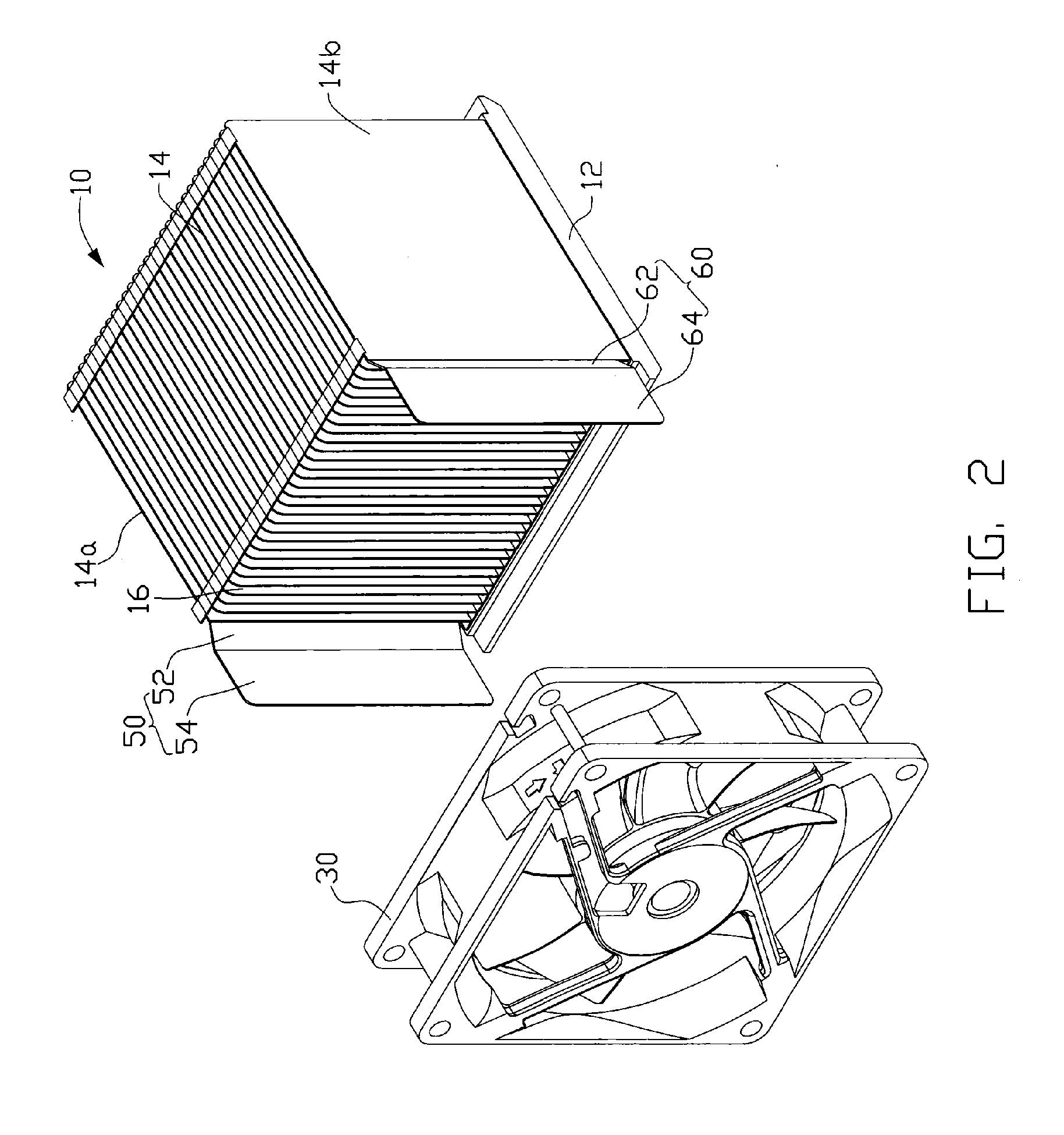
[0013] As shown in FIG. 1 and FIG. 2, a heat dissipation device in accordance with the present invention includes a heat sink 10, a fan 30 disposed at one side of the heat sink 10 with a space formed between the heat sink 10 and the fan 30, and two airflow guiding boards 50, 60 extending through the space to connect with the fan 30.
[0014] The heat sink 10 comprises a base 12 for contacting with a heat source (not shown) such as a central processing unit (CPU) and a plurality of fins 14 arranged on the base 12. The fins 14 vertically extend upwardly from the base 12. The fins 14 are made of heat conductive material. The fins 14 are spaced apart from each other with a same distance. A channel 16 is therefore formed between each two adjacent fins 14. In order to transfer the heat absorbed from the heat source by the heat sink 10 sufficiently, the fan 30 is disposed on a rear side of the heat sink 10. A width of the heat sink 10 is less than that of the fan 30, resulting in the flange o...
third embodiment
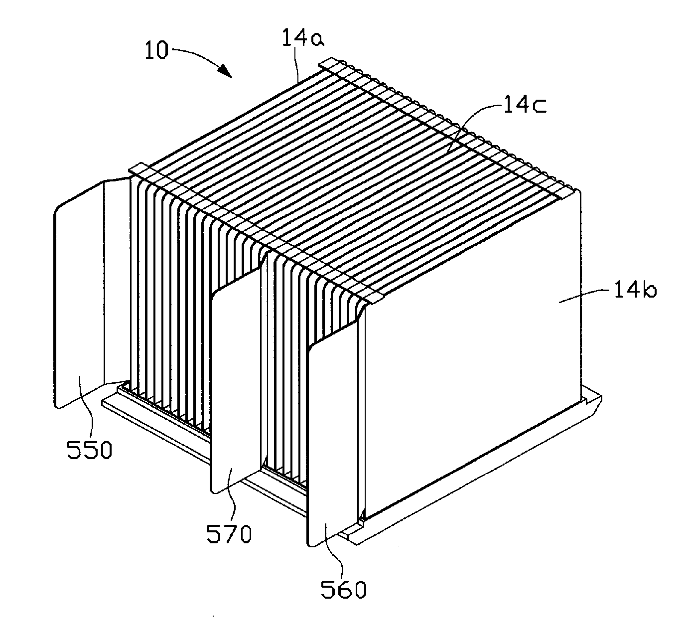
[0019] A heat dissipation device in accordance with the present invention is shown in FIG. 5 and FIG. 6. The heat dissipation device comprises a heat sink 10, a fan 30 disposed at one side of the heat sink 10 with a space formed between the heat sink 10 and the fan 30 and airflow guiding boards 550, 560, 570 extending through the space to connect with the fan 30. The airflow guiding boards 550, 560 are formed at opposite two outmost sides of the heat sink 10, while the airflow guiding board 570 is formed by extending a fin 14c inside the heat sink 10 to the fan 30. The fin 14c can be any one of the fins between the two outmost fins 14a, 14b. In this embodiment, the airflow guiding board 570 deviates the middle of the heat sink 10, dividing the space into two parts different in size, of which the relatively large one corresponds to other heat generating components such as a heat sink 90 for a voltage regulator. The heat sink 90 is mounted in front of the heat sink 10. The airflow flo...
PUM
 Abstract
Description
Claims
Application Information
 - R&D
- Intellectual Property
- Life Sciences
- Materials
- Tech Scout
- Unparalleled Data Quality
- Higher Quality Content
- 60% Fewer Hallucinations
Browse by: Latest US Patents, China's latest patents, Technical Efficacy Thesaurus, Application Domain, Technology Topic, Popular Technical Reports.
© 2025 PatSnap. All rights reserved.Legal|Privacy policy|Modern Slavery Act Transparency Statement|Sitemap|About US| Contact US: help@patsnap.com


