
Single-side ultrasonic inspection systems and methods

a single-side, ultrasonic inspection technology, applied in the direction of instruments, heat measurement, specific gravity measurement, etc., can solve the problems of inconvenient moving of equipment in the interior to inspect the stiffening members in the obstructed interior of the vehicular structure, and the manufacturing efficiency of many kinds of structures is at odds, so as to achieve the effect of disassembly of the structure under inspection

Active Publication Date: 2007-05-03
THE BOEING CO
View PDF14 Cites 16 Cited by
  • Summary
  • Abstract
  • Description
  • Claims
  • Application Information

AI Technical Summary

Benefits of technology

[0006] Embodiments of the invention address the above needs and achieve other advantages by providing an ultrasonic inspection system that is capable of single-sided inspection. In particular, the ultrasonic inspection system is capable of inspecting a channel member through a skin, where the channel member and inspection system are disposed on opposite sides of the skin. The inspection system incorporates a first ultrasonic transducer that sends ultrasonic waves into the channel member through the skin, and a second ultrasonic transducer that receives ultrasonic waves from the channel mem

Problems solved by technology

Durability, strength, and reliability are goals that often oppose efficiency in the manufacturing of many sorts of structures.
A vehicle component such as the fuselage or a wing of an airplane, however, typically has an interior that is partially or wholly obstructed with such things as electrical wires, ventilation ducts, actuating cables, hydraulic control lines, fuel lines, and insulation materials.
Thus, inspecting stiffening members in the obstructed interior of a vehicular structure by moving equipment about in the interior is not always convenient, particularly where flight schedules may be affected.

Method used


Image

  • Single-side ultrasonic inspection systems and methods
  • Single-side ultrasonic inspection systems and methods
  • Single-side ultrasonic inspection systems and methods

Examples


Embodiment Construction

[0021] The present invention now will be described more fully hereinafter with reference to the accompanying drawings, in which some, but not all embodiments of the invention are shown. Indeed, the invention may be embodied in many different forms and should not be construed as limited to the embodiments set forth herein; rather, these embodiments are provided so that this disclosure will satisfy applicable legal requirements. Like numbers refer to like elements throughout.

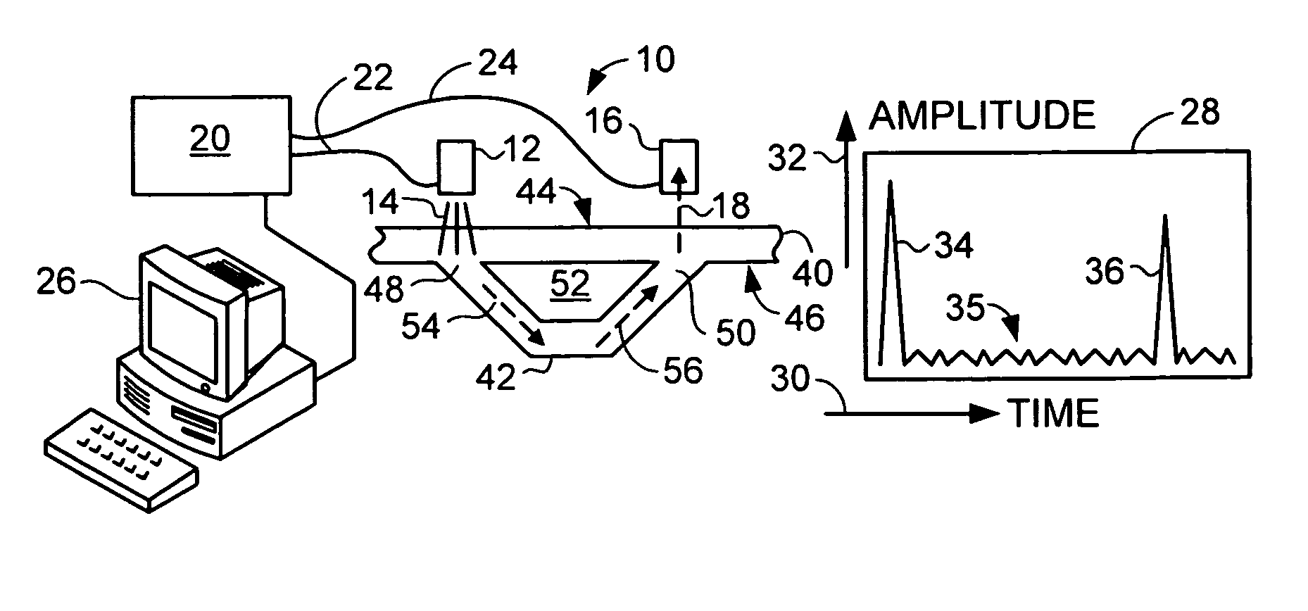
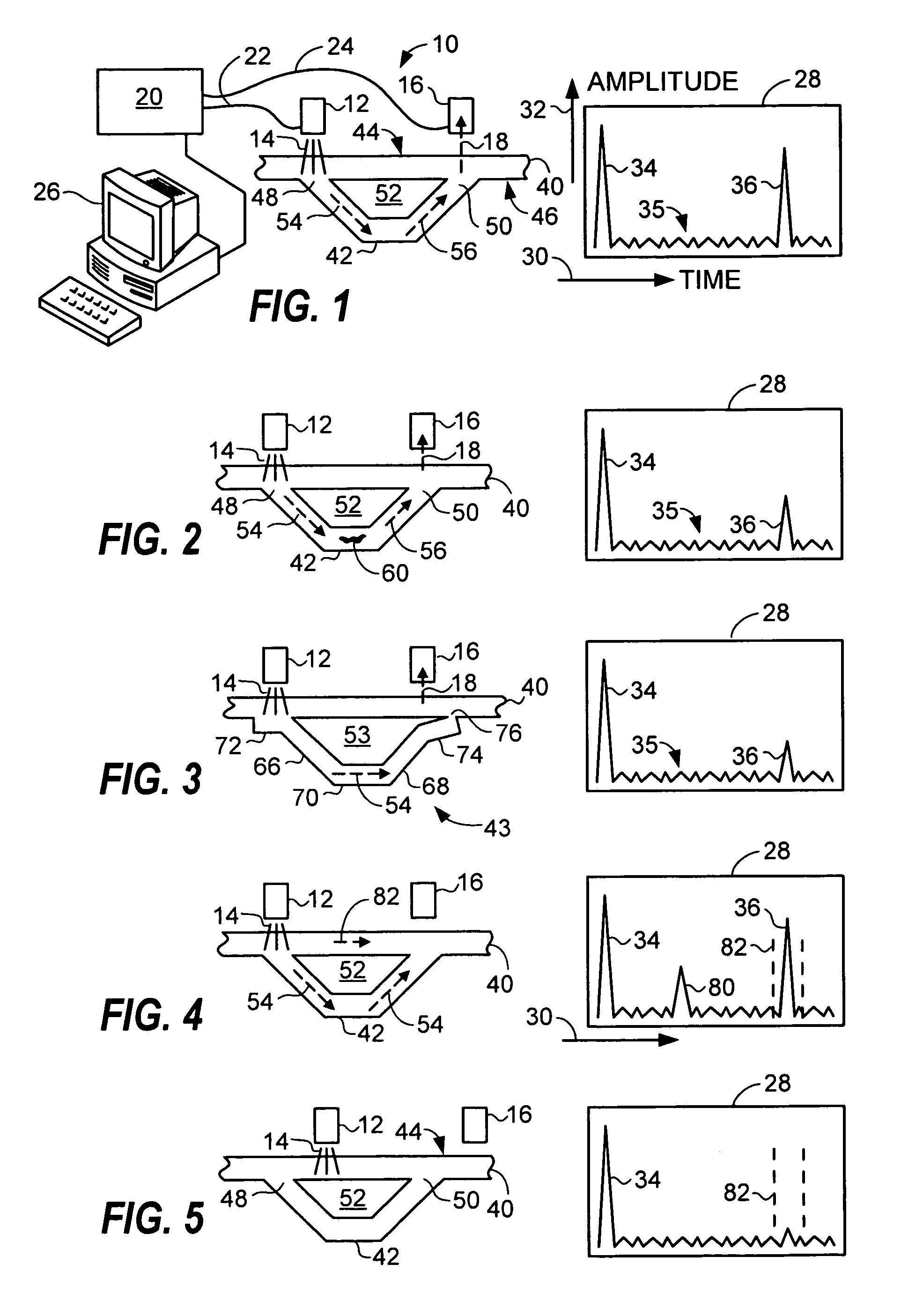
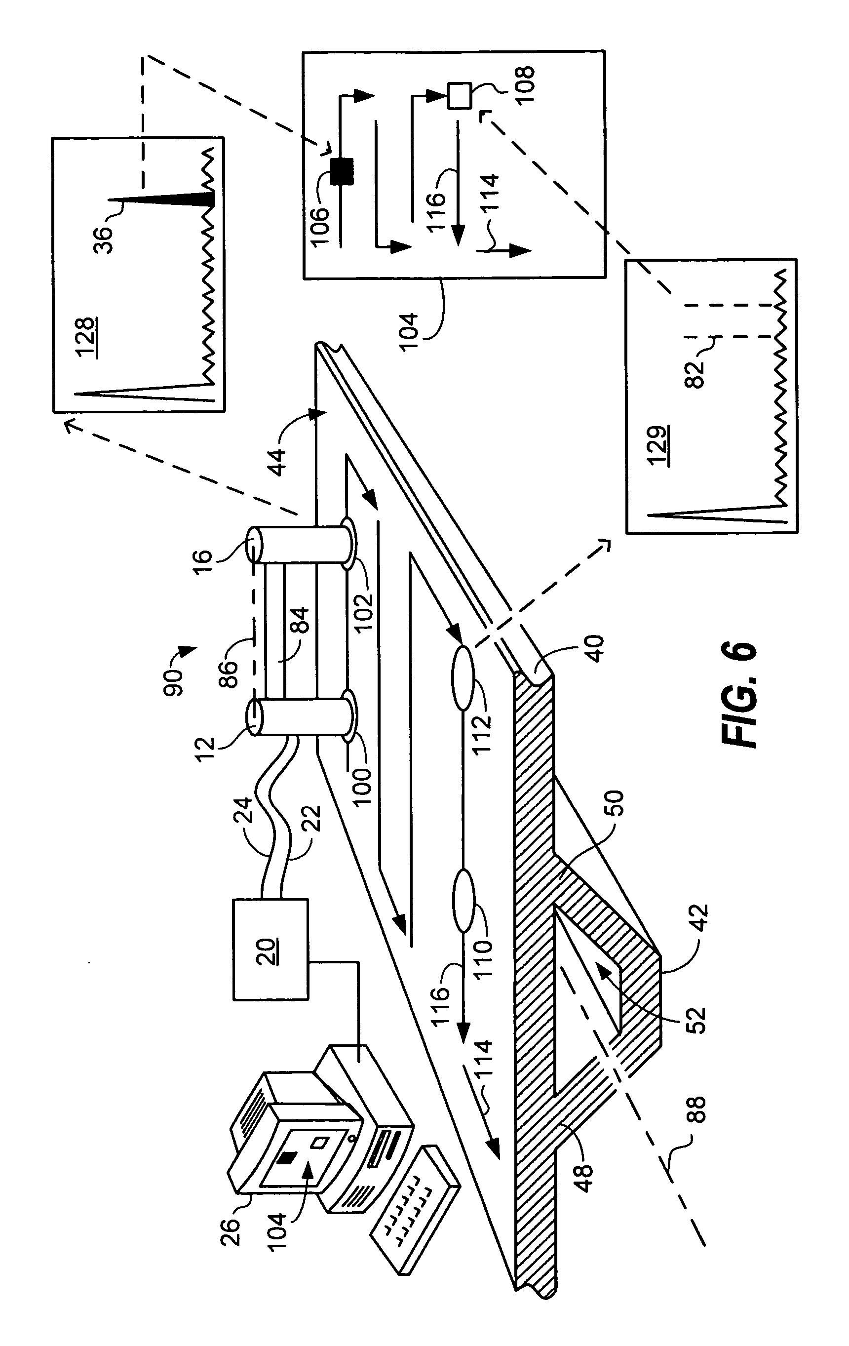
[0022] Referring now to the drawings, an ultrasonic inspection system 10 is shown that includes a first ultrasonic transducer 12 that generally transmits ultrasonic signals 14, a second ultrasonic transducer 16 that generally detects ultrasonic signals 18, a controller 20 that is electronically coupled to the first and second transducers by one or more wireless devices or by respective cabled connections 22 and 24, and a display system 26 electronically coupled to the controller 20. The display system 26 may be a...


PUM


Abstract

Ultrasonic systems and methods for inspecting a channel member through a skin or panel are provided. The channel member may be a stiffener for an aircraft component such as a trapezoidal stringer attached to a skin of an aircraft fuselage. Transducers of the system are disposed on a side of the skin opposite the channel member. Ultrasonic waves generated on a first side of a skin propagate through the skin, across a channel member attached to a second side of the skin, and through the skin again to be received on the first side of the skin. Times of flight are measured for the collection of time-gated data. A two dimensional C-scan is generated for identifying flaws and irregularities in a structure by way of single-side ultrasonic non-destructive inspection (NDI).

Description

FIELD OF THE INVENTION [0001] Embodiments of the present invention relate generally to non-destructive inspection devices and methods. More particularly, embodiments of the invention relate to devices and methods for the single-sided ultrasonic inspection of a stiffener attached to a panel. BACKGROUND OF THE INVENTION [0002] Durability, strength, and reliability are goals that often oppose efficiency in the manufacturing of many sorts of structures. In order to be both commercially viable and safe, vehicle components in particular should be both light weight and structurally sound. In meeting both challenges, modern vehicle components such as aircraft fuselages and wings are often designed to include thin external skins and stiffening members attached to the skins within the interiors of the components. The integrity of such a component relies on the condition of the skin, the condition of the stiffening member, and on the condition of the bond joining the two. Ultrasonic non-destru...

Claims


Application Information

Patent Timeline
IPC IPC(8): G01N29/00
CPCG01N29/0645G01N29/07G01N29/11G01N29/265G01N29/38G01N2291/048G01N2291/102G01N2291/2694
Inventor KOLLGAARD, JEFFREY R.
Owner THE BOEING CO
Learn More