
Shooting stick and sling combination

a technology of shooting sticks and slings, applied in the field of shooting supports, can solve the problems of shooting sticks that are easy to be lost, misplaced during transportation, simply laid down and forgotten, and shooting sticks that take a substantial amount of time to assemble, and achieve the effect of improving the shooting suppor

Inactive Publication Date: 2007-05-03
RUSH RHETT P +1
View PDF17 Cites 62 Cited by
  • Summary
  • Abstract
  • Description
  • Claims
  • Application Information

AI Technical Summary

Benefits of technology

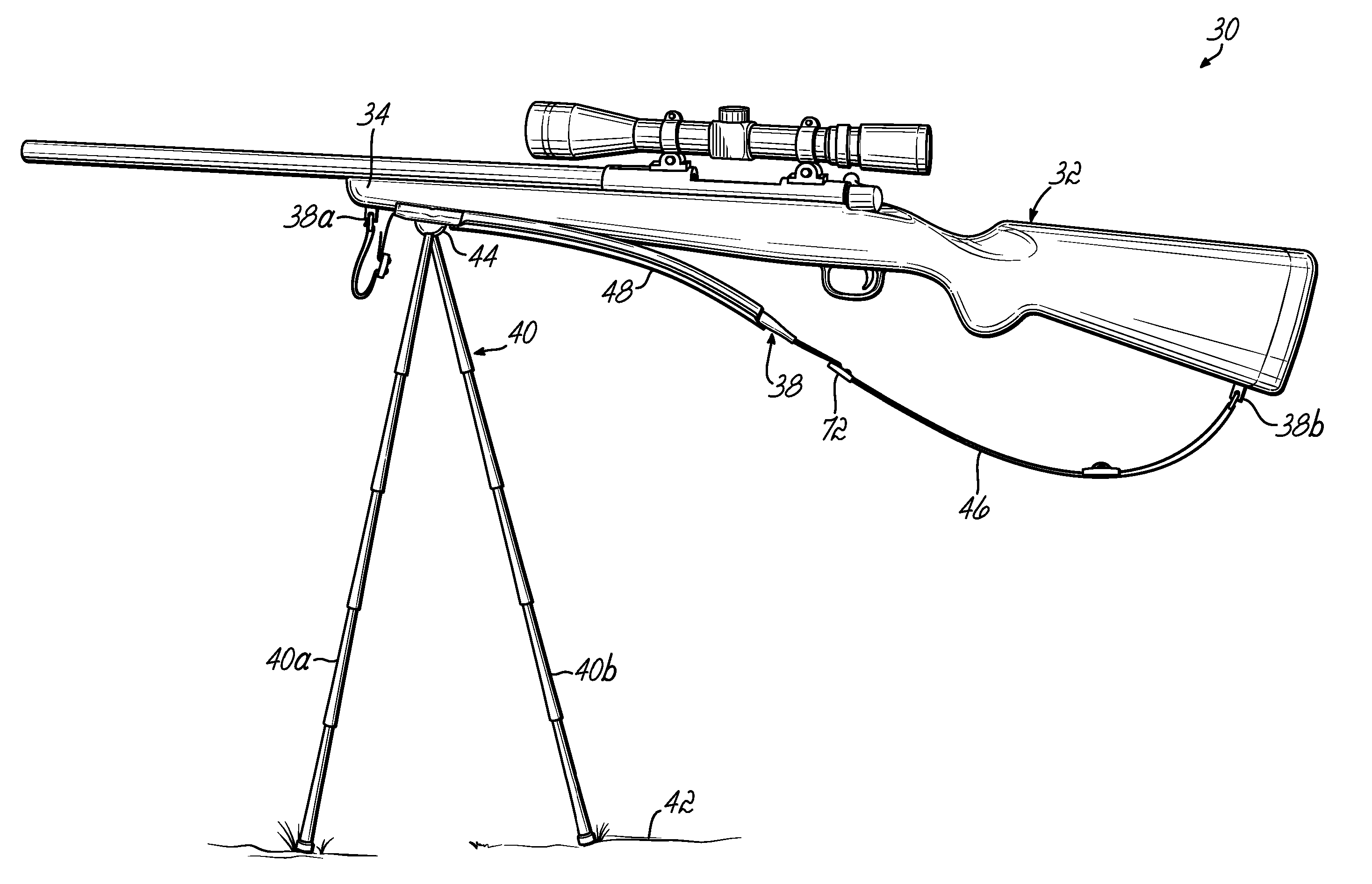
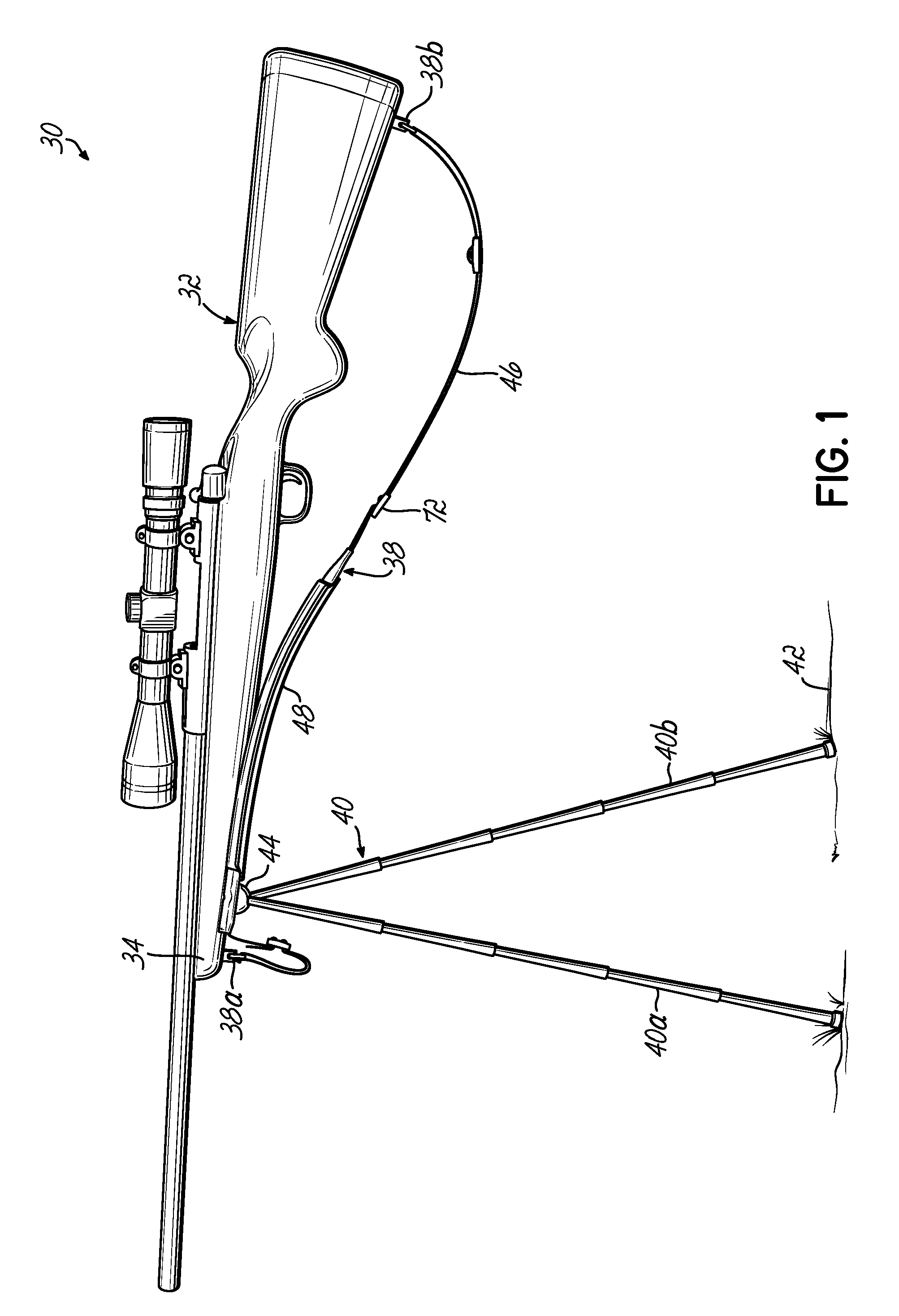
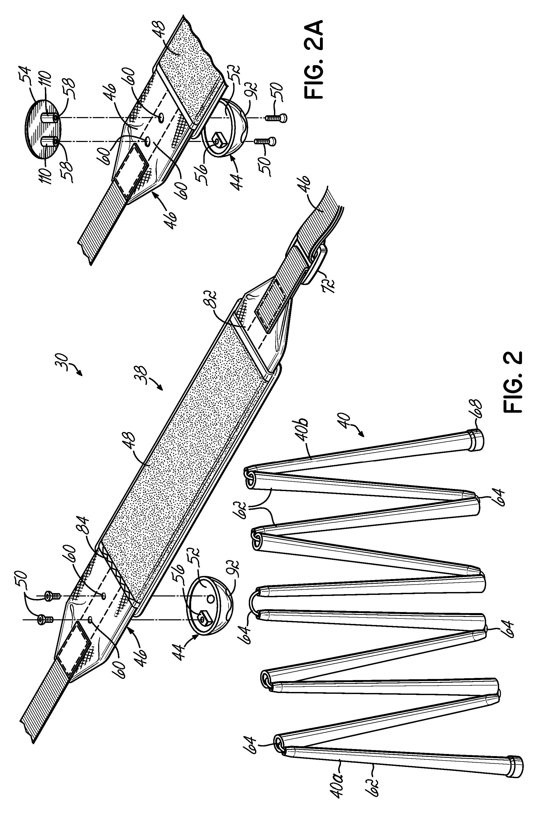
[0010] To these ends and in accordance with a preferred embodiment of the invention, a shooting support of monopod, bipod, or other configuration, including collapsible legs, is mounted directly to a sling used for carrying the weapon. The legs are quickly and easily erected to deployed configurations, and the weapon can be rested on the sling proximate the mounting structure for the legs for support. The sling includes a cover, sleeve, or pouch for housing the collapsed legs in stored or non-deployed condition on the sling. The sling is operatively coupled to the weapon for enabling conventional transport of the weapon by a user and the shooting support is operatively coupled to the sling, in stored condition but is quickly deployed for use.
[0011] The shooting support is preferably constructed with a base secured to the sling and having one or more concave sockets receiving the respective movable ends of one or more collapsible legs or sticks so that, when deployed, the rifle can be moved to follow a target without loss of support from the stick or sticks.

Problems solved by technology

One drawback of using these collapsible shooting sticks is that the shooting sticks are easily lost.
In addition, they can be misplaced during transport or simply laid down and forgotten.
Furthermore, some shooting sticks take a substantial amount of time to assemble.
Such devices are provided primarily in bipod configurations, and tend to be relatively heavy and somewhat unwieldy, making the weapon harder to carry and to handle.

Method used


Image

  • Shooting stick and sling combination
  • Shooting stick and sling combination
  • Shooting stick and sling combination

Examples


Embodiment Construction

[0034] In all of the illustrations of the application, identical numeral reference characters are used to denote identical parts. In addition, for some of the embodiments the same numeric reference character with a prime (′) symbol added identifies parts that are very similar in structure and function, but not identical to parts of other embodiments.

[0035] As used herein, and unless otherwise defined, the terms “shooting stick” refers to a shooting support or support apparatus as described herein of monopod, bipod, tripod or other leg configurations.

[0036] While the invention finds particular use with elongated firearms such as rifles, it could be used with other forms of weapons or firearms, or other forms of user-manipulated elements or devices where steadiness is desired. These could range from optics, cameras, tools and many other devices.

[0037]FIG. 1 illustrates a support apparatus preferably comprising a shooting stick apparatus in a shooting stick and sling combination 30 ...


PUM


Abstract

A selectively collapsible shooting support is mounted on a sling for supporting a weapon to which the sling is attached. A cover is selectively moveable with respect to the sling for concealing and housing the collapsed shooting support in stored condition on the sling, and for releasing the support for deployment. The shooting support preferably comprises two segmented or collapsible sticks connected to the sling and extendable to support a firearm during firing. Movement of the firearm to follow a target is possible without loss of support or repositioning of the sticks on a support surface or a body portion of a shooter.

Description

CROSS REFERENCE TO RELATED AAPLICATIONS [0001] Benefit is claimed of the filing date of Nov. 1, 2005 of applicant's co-pending expressly incorporated herein in its entirety.TECHNICAL FIELD OF THE INVENTION [0002] The present invention relates to shooting supports and more particularly, but not exclusively, to shooting sticks for use to steady a firearm for accurate shooting. BACKGROUND OF THE INVENTION [0003] Shooting supports, known as shooting sticks, are well known in the art. Present shooting sticks are used with a weapon to support and hold steady the firearm, such as an elongated rifle, or other form of firearm, during firing. Known shooting sticks come in a variety of different configurations. For example, a shooting support can be in the form of a monopod, bipod or tripod configuration for example. These are either directly attached to a rifle by a variety of devices, or comprise separate support devices on which the rifle is rested. By placing the rifle on top of the shooti...

Claims


Application Information

Patent Timeline
IPC IPC(8): F41C27/00F41C33/00F41C23/02
CPCF16M11/16F16M11/40F41A23/02F41C33/002F16M11/242F16M11/38F16M13/04
Inventor RUSH, RHETT P.ELLINGTON, RANDAL CRAIG
Owner RUSH RHETT P
Learn More