
Fault Management of HTS Power Cable

a technology of fault management and power cable, which is applied in the direction of emergency protective arrangements, programme control, instruments, etc., can solve the problems of voltage collapse, affecting the distribution of power throughout the network, and reducing the energy available for distribution throughout other areas

Active Publication Date: 2007-04-26
AMERICAN SUPERCONDUCTOR +1
View PDF8 Cites 28 Cited by
  • Summary
  • Abstract
  • Description
  • Claims
  • Application Information

AI Technical Summary

Benefits of technology

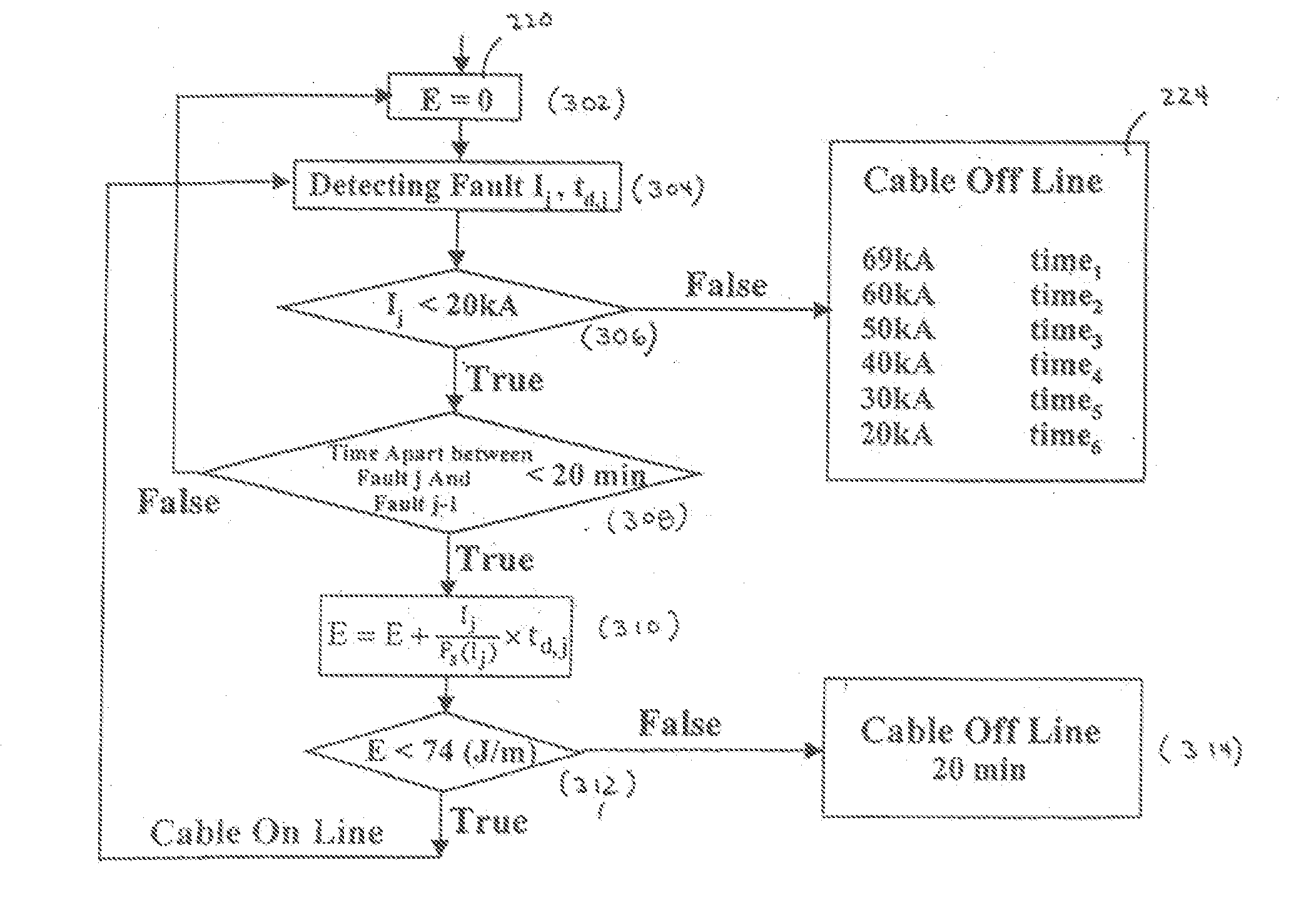
The invention provides a method and system for protecting a superconducting electrical cable in a utility power network by detecting fault currents and determining if to disconnect the cable based on the energy dissipated from the fault. The system includes a sensor and controller that can detect and determine the magnitude and duration of fault currents, and if the energy dissipated exceeds a predetermined threshold, the controller will disconnect the cable from the network for a time period to prevent damage. This method and system can provide over-current protection of superconducting electrical cables by accounting for previous faults and heating effects, and can help prevent damage to the cable caused by heating from other recent faults.

Problems solved by technology

Problems in a utility network, or “faults”, (such as network device failures) can affect how power is distributed throughout the network.
In particular, faults tend to drain energy from power sources, leaving less energy for distribution throughout other areas of the network and for recovering from voltage “sags” resulting from the fault.
When a fault occurs in a utility network, momentary voltage depressions are experienced, which may result in voltage collapse or voltage instability on the network.
In general, such a fault appears as an extremely large load materializing instantly on the utility network.
First, a cold dielectric HTS power cable requires that the cooling liquid must remain in a sub-cooled state during a major fault or multiple through faults.
Any bubble formation inside dielectric will threaten the dielectric properties of the insulation.
As a result, conventional cable fault protection schemes are not suitable for use with HTS power cables.

Method used


Image

  • Fault Management of HTS Power Cable
  • Fault Management of HTS Power Cable
  • Fault Management of HTS Power Cable

Examples


Embodiment Construction

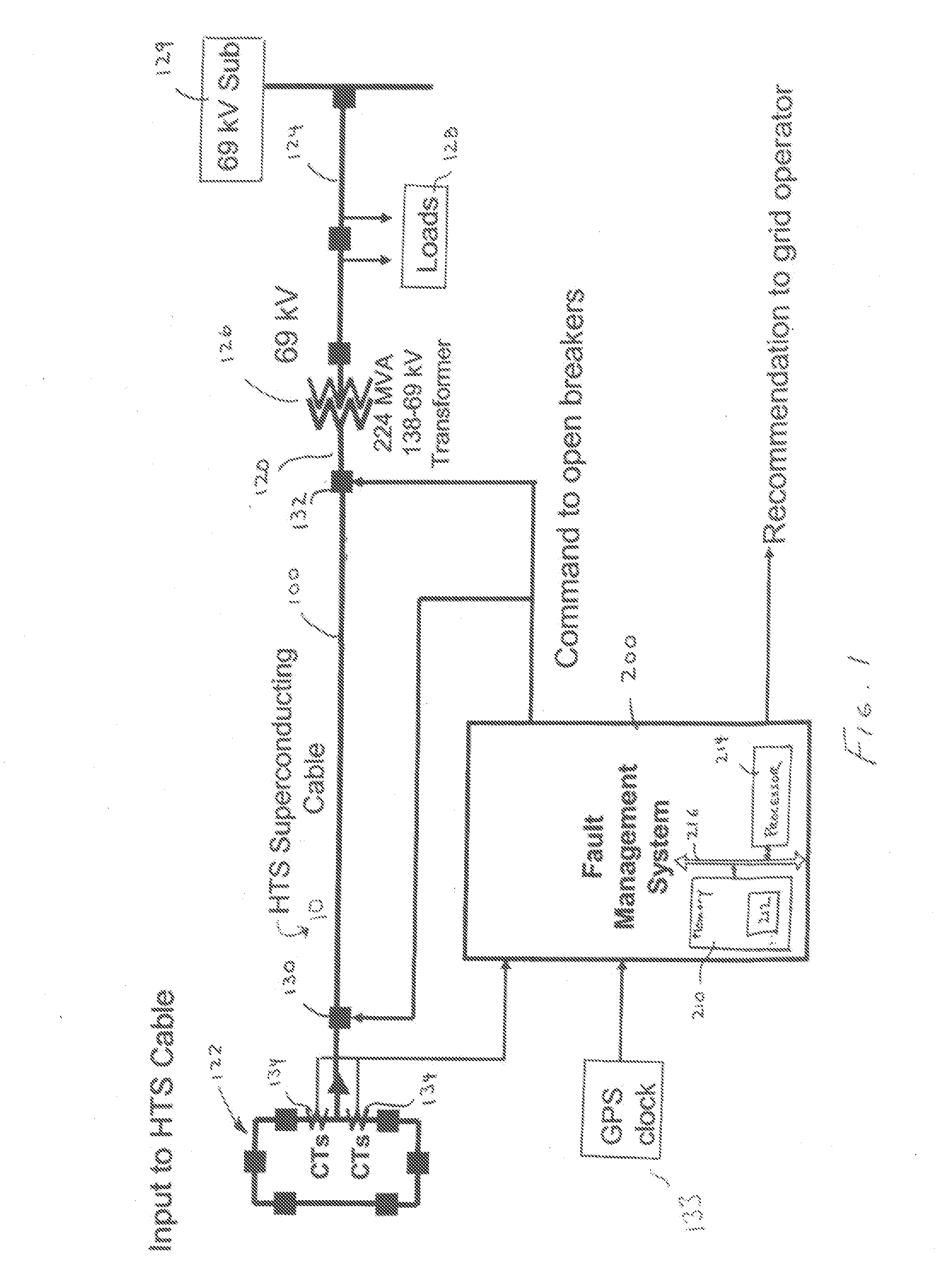
[0020] Referring to FIG. 1, a high temperature superconductor (HTS) cable 100 is shown connected within a portion of a utility power grid 10. HTS cable 100 has a length here of several hundred meters and provides a relatively high current and low resistance electrical path while occupying a fraction of the space required by a conventional copper cable carrying the same amount of current. As will be discussed in greater detail below, HTS wire used in HTS cable 100 has a design and structure capable of carrying as much as 150 time the electrical current of similar sized copper wire. With a relatively small amount of HTS wire rather than large quantities of copper stranded into the core of an AC cable, three to five times more power can be carried through an equivalent sized line.

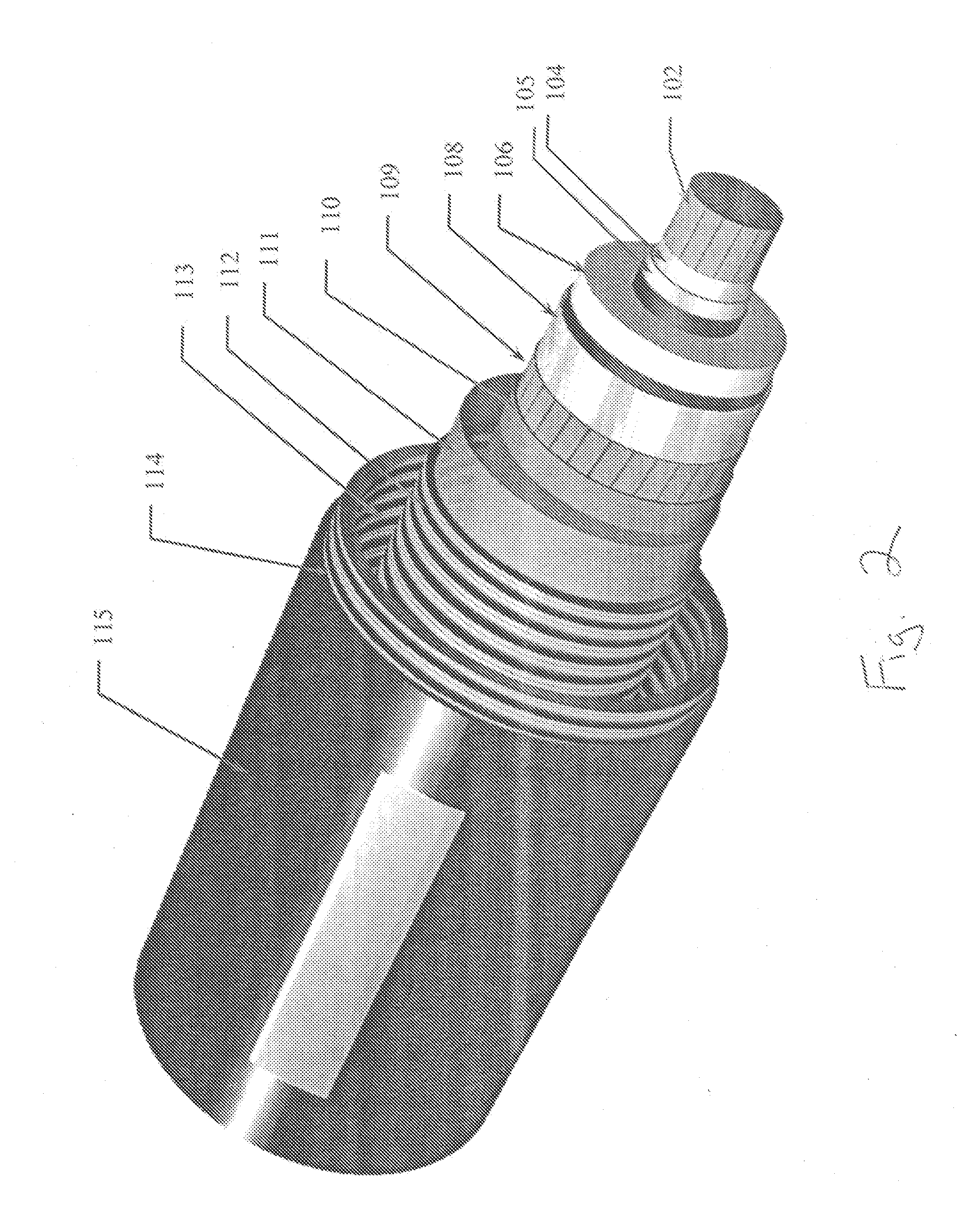
[0021] Referring to FIG. 2, HTS cable 100 includes a strand copper core 102 surrounded in radial succession by a first high temperature superconductor layer 104, a second high temperature superconductor layer...


PUM


Abstract

A method and system for providing protection for a superconducting electrical cable located in a utility power network includes detecting a fault current on the superconducting electric cable, determining the cumulative total energy dissipated in the superconducting electrical cable from the fault current and at least one prior fault current over a predetermined time period, and determining whether to disconnect the superconducting electrical cable from the utility power network on the basis of the cumulative total energy dissipated.

Description

RELATED APPLICATION [0001] Under 35 U.S.C. §119(e)(1), this application claims the benefit of prior U.S. provisional application 60 / 703,855, filed Jul. 29, 2005.GOVERNMENT RIGHTS [0002] This invention was made with U.S. government support under Contract No.; DE-FC36-03G013032. The Government may have certain rights in the subject invention.BACKGROUND OF THE INVENTION [0003] Problems in a utility network, or “faults”, (such as network device failures) can affect how power is distributed throughout the network. In particular, faults tend to drain energy from power sources, leaving less energy for distribution throughout other areas of the network and for recovering from voltage “sags” resulting from the fault. [0004] When a fault occurs in a utility network, momentary voltage depressions are experienced, which may result in voltage collapse or voltage instability on the network. [0005] In general, such a fault appears as an extremely large load materializing instantly on the utility n...

Claims


Application Information

Patent Timeline
Patent Type & Authority Applications(United States)
IPC IPC(8): G01R31/00
CPCH02H6/005Y02E40/68H02H7/001Y02E40/60H02H7/26G01R31/08
Inventor YUAN, JIEMAGUIRE, JAMES F.ALLAIS, ARNAUDSCHMIDT, FRANK
Owner AMERICAN SUPERCONDUCTOR
Learn More