System and method for troubleshooting a machine

a technology of system and method, applied in the field of system and method for troubleshooting a machine, can solve the problems of unnecessary increase in tooling cost and/or production time loss, relatively complex process that requires highly trained individuals to properly execute the analysis, and loss of production tim

Inactive Publication Date: 2007-04-19
FORD MOTOR CO
View PDF71 Cites 26 Cited by
  • Summary
  • Abstract
  • Description
  • Claims
  • Application Information

AI Technical Summary

Benefits of technology

The present invention provides a troubleshooting system for machines that uses a tiered structure and an information screen to help operators analyze and fix problems with machines. The system can also send alarm and warning messages to a plant floor information system and allow operators to input answers to questions to quickly pinpoint the problem. The technical effect of this invention is to improve the efficiency and effectiveness of troubleshooting systems for machines.

Problems solved by technology

The technical problem addressed in this patent text is the need for a system and method to troubleshoot machines using data that is automatically gathered and processed while the machine is operating, without requiring highly trained personnel or taking the machine offline. The system should include a tiered analysis structure starting with an initial analysis performed by the machine operator and moving through increasing levels of analytical sophistication.

Method used


Image

  • System and method for troubleshooting a machine
  • System and method for troubleshooting a machine
  • System and method for troubleshooting a machine

Examples


Embodiment Construction

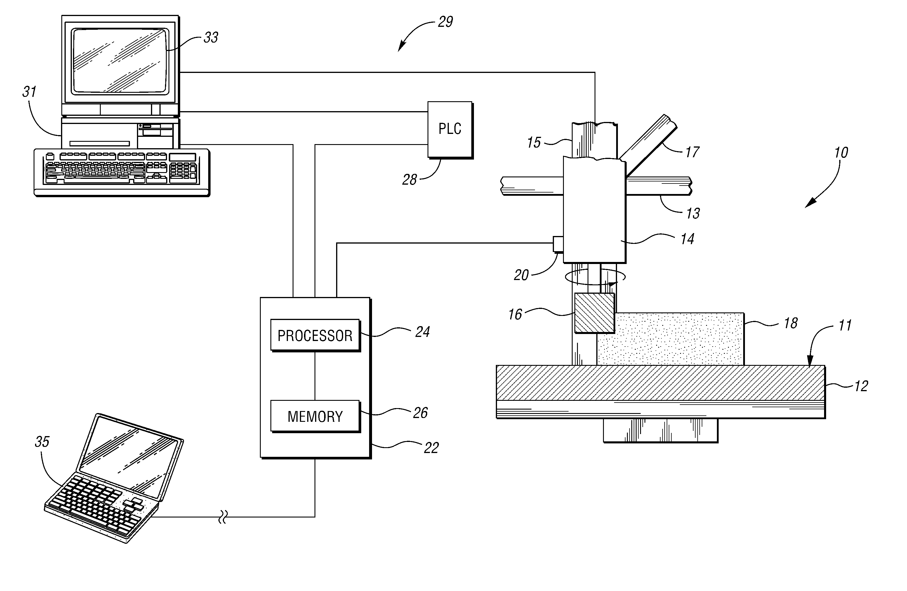
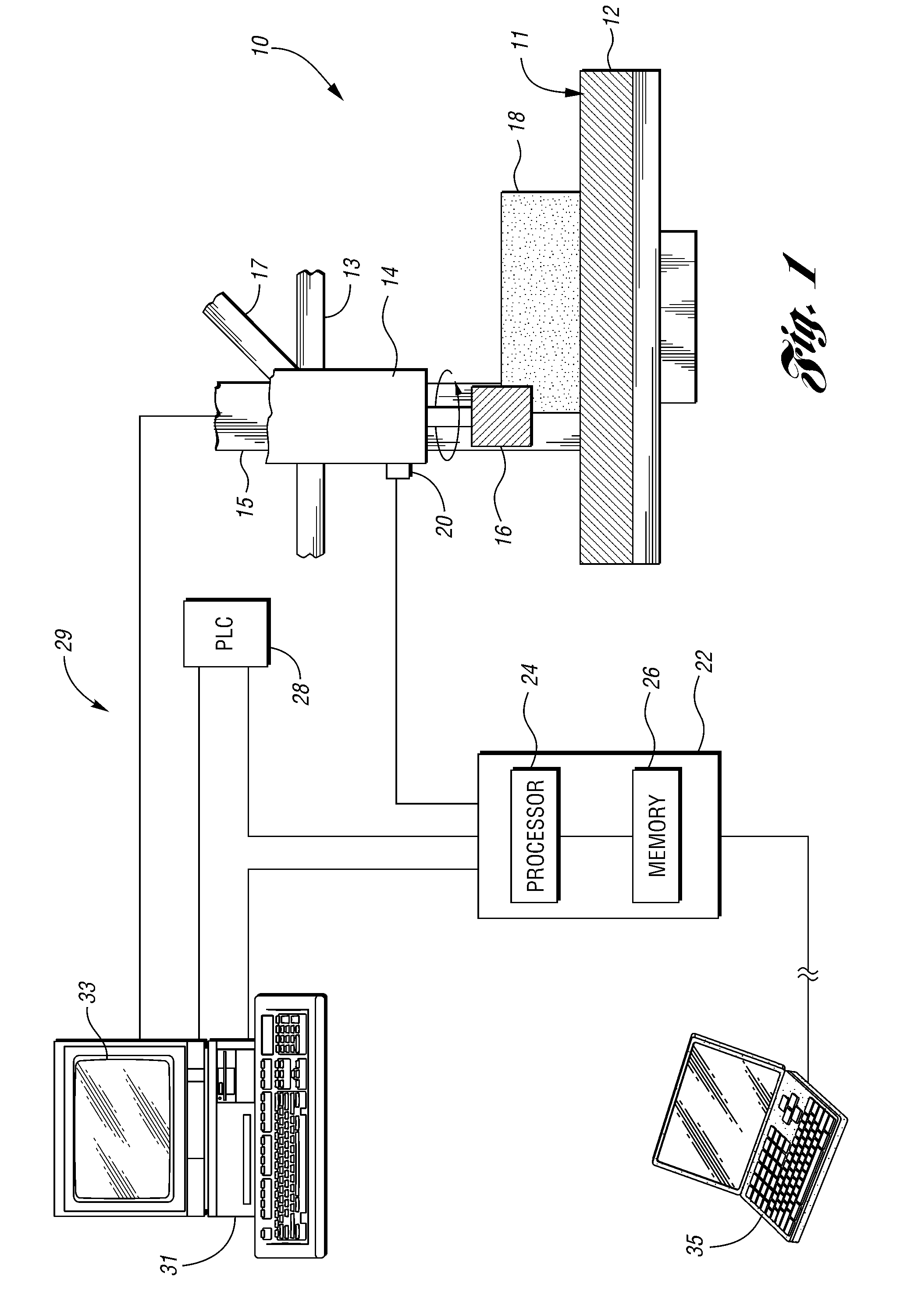
[0019]FIG. 1 illustrates a system 10 for troubleshooting operation of a manufacturing machine, or machine tool 11. The machine tool 11 includes a bed 12 and a spindle 14. In addition, there are three slides 13, 15, 17, which are operable to effect a movement of the spindle 14 along an x-axis, a y-axis, and a z-axis, respectively. Of course, a machine tool may have slides for effecting movements of other portions of the machine tool; for example, slides 19, 21 facilitate movement of the bed 12 of the machine tool 11. The machine tool 11, shown in FIG. 1, is a computer numerical control (CNC) milling machine. As will readily be discerned from the description below, the present invention can be used with virtually any type of machine tool, including manual as well as CNC machines.

[0020] Mounted in the spindle 14 is a cutting tool 16 which is used to machine a workpiece 18. Attached to the spindle 14 is a vibration sensor 20 that is configured to sense vibrations in the spindle 14 and ...


PUM


Abstract

A system and method for troubleshooting a operation of a machine include performing an initial, operator based analysis in response to an alarm indicator output by a processing unit monitoring the machine operation. The method uses a query-based analysis to guide the operator. A secondary analysis is used if the initial analysis does not yield the cause of the alarm. The secondary analysis can include a number of steps, including analyzing raw vibration data or trend lines generated from the raw data. If the trend lines are operation specific, a particular operation or particular tool may be identified as the cause of the alarm, and appropriate action can be taken. A tertiary analysis can also be used if the initial and secondary analyses do not yield the cause of the alarm.

Description


Claims


Application Information

Patent Timeline
Owner FORD MOTOR CO
Why Eureka
Try Eureka