Refining surface and a blade segment for a refiner

a technology of a refiner and a blade segment, which is applied in the field of refining surface, can solve the problems of limiting the groove volume even more, affecting the refining process, and affecting the refining process, and achieves the effect of increasing the refining capacity

Active Publication Date: 2007-04-19
VALMET TECH INC
View PDF10 Cites 18 Cited by
  • Summary
  • Abstract
  • Description
  • Claims
  • Application Information

AI Technical Summary

Benefits of technology

[0012] Embodiment of the present invention provide a new refining surface or blade solution for a refiner, enabling a higher refining capacity than previously.
[0016] With the solution of the invention, a high cutting length can be achieved on the refining surface. Since the first grooves have a volume that is larger than previously, an optimal, steady feed of the fibrous material to be refined can be achieved over the entire area of the refining surface. The refining surface of the solution can thus provide both the desired capacity and a good quality of the refined pulp. Unlike before, the same refining surface solution can also be applied to the refining of both long and short fibers.

Problems solved by technology

However, there is a small clearance between the rotor bars and stator bars of the refiner, and the fibrous material is mainly ground or refined between them.
This limits the groove volume even more.
In addition, in cast blades the groove surfaces are rough, which causes flow resistance to the fibrous material to be refined.
A problem of these “dense blades” is, therefore, that they tend to be blocked.
On the other hand, even the above mentioned blade solutions have not been successful in increasing the refiner capacity in a desired way.
With these discharge channels, it has been possible to diminish the problems caused by steam generated during refining in the refining process, but the discharge channels may, however, make the refining more uneven and, in practice, the steam discharge channels described in the publication are arranged too sparsely with respect to each other.
Said grooves on the upper surface of the blade bar also add to the combined cutting length of the bars of the refining surface to some extent, but, in practice, the oblique structure of the upper surface of the blade bar hinders these small grooves from participating in the refining of the material before the blade bar has worn significantly, which means that one has not, nevertheless, succeeded in substantially increasing the refining capacity of the refiner.

Method used


Image

  • Refining surface and a blade segment for a refiner
  • Refining surface and a blade segment for a refiner
  • Refining surface and a blade segment for a refiner

Examples


Embodiment Construction

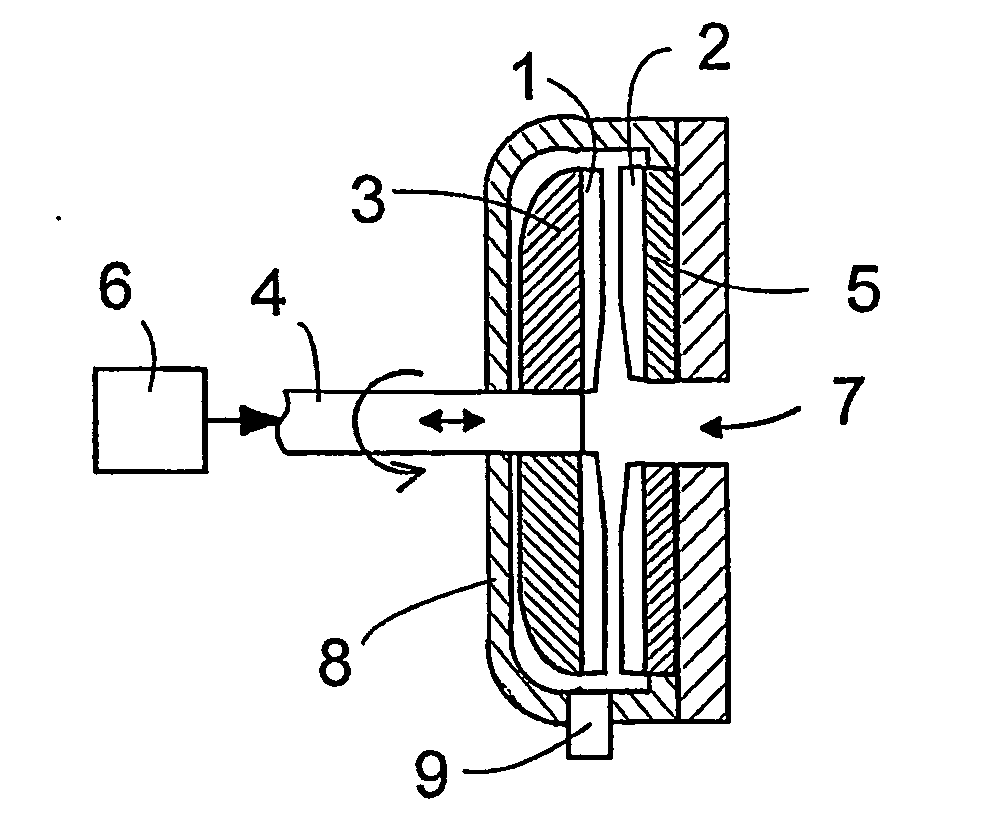
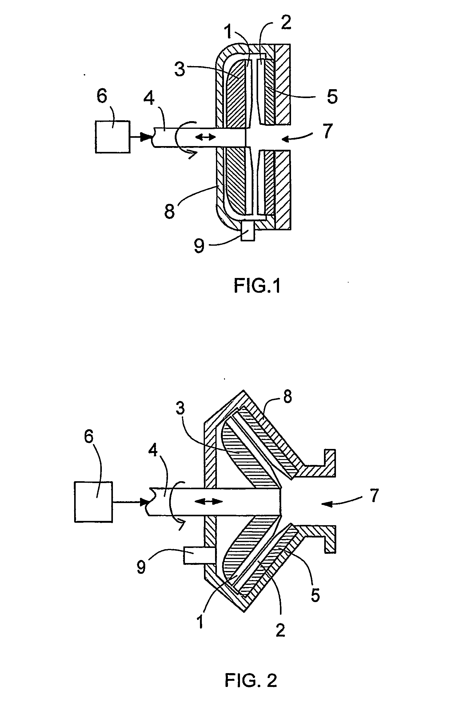
[0040]FIG. 1 shows schematically a side view of a typical disc refiner in cross-section. The disc refiner comprises two disc-like refining surfaces 1 and 2 of adjacent refining members, which are positioned coaxially relative to each other. In this embodiment, the first refining surface 1 is in a rotating refiner disc or refining member 3, i.e. a rotor, which is rotated by a shaft 4. The second refining surface 2 is in this case in a fixed refiner disc or refining member 5, i.e. a stator. The refining surfaces 1 and 2 of the refiner discs 3 and 5 may be either formed directly onto the discs or formed of separate blade segments in a manner known per se. FIG. 1 shows further a loader 6 connected to affect the refiner disc 3 via the shaft 4 in such a way that it can be pushed towards the refiner disc 5 to adjust the gap between them. The refiner disc 3 is rotated via the shaft 4 in a manner known per se by means of a motor not shown for the sake of clarity.

[0041] The lignocellulose-co...


PUM

PropertyMeasurementUnit
depthaaaaaaaaaa
depthaaaaaaaaaa
widthaaaaaaaaaa

Abstract

A refining surface of a refining member, adapted for use with a refiner for defibrating a lignocellulose-containing material, is provided. Such a refining surface comprises a plurality of first grooves, each first groove being defined between two adjacent first bar portions of the refining surface, and extending between opposing first and second radial edges of the refining surface. The refining surface further comprises a plurality of second grooves, each second groove being defined between two adjacent second bar portions of the refining surface forming each first bar portion, and extending between two adjacent second grooves. The first bar portions are wider than the second bar portions, and each second bar portion are between about 1 mm and about 3 mm wide. A blade segment of a refining member is also provided.

Description

BACKGROUND OF THE INVENTION [0001] 1. Field of the Invention [0002] The invention relates to a refining surface of a refining member for a refiner intended for defibrating lignocellulose-containing material, the refiner comprising at least two refining surfaces arranged coaxially relative to each other, at least one of which refining surfaces is arranged to rotate around a shaft, and between which refining surfaces the material to be defibrated is fed, and which refining surface comprises first bars extending from the inner circumference of the refining surface to the outer circumference of the refining surface and between them first grooves, and the upper surfaces of which first bars further comprise second grooves connecting said first grooves, and between which second grooves there are second bars. [0003] The invention further relates to a blade segment of a refining member for a refiner intended for defibrating lignocellulose-containing material, the refiner comprising at least ...

Claims


Application Information

Patent Timeline
Patent Type & Authority Applications(United States)
IPC IPC(8): B02C7/04B02C7/12
CPCB02C7/12
Inventor SJOSTROM, HAKANARJANMAA, VESAFROBERG, PERVUORIO, PETTERIVIRVING, NILSHUHTANEN, JUHA-PEKKAKAARINEVA, MATTI
Owner VALMET TECH INC
Why Eureka
Try Eureka