
Balloon catheter

a balloon catheter and balloon technology, applied in balloon catheters, other medical devices, surgery, etc., can solve the problems of preventing designers from developing new rapid exchange catheter implementations, relatively restricted implementations, etc., and achieve the effect of preventing internal pressure changes

Inactive Publication Date: 2007-04-12
ANGIOSLIDE
View PDF62 Cites 71 Cited by
  • Summary
  • Abstract
  • Description
  • Claims
  • Application Information

AI Technical Summary

Benefits of technology

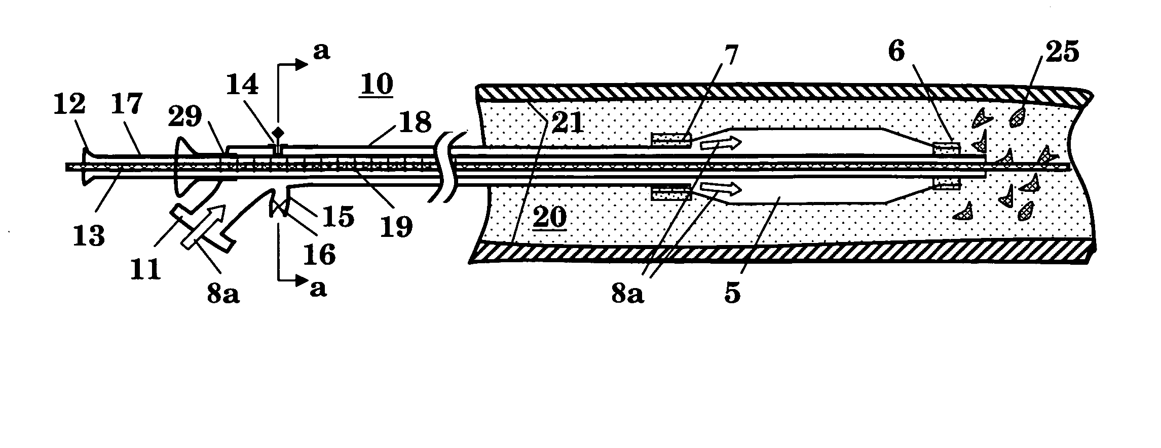
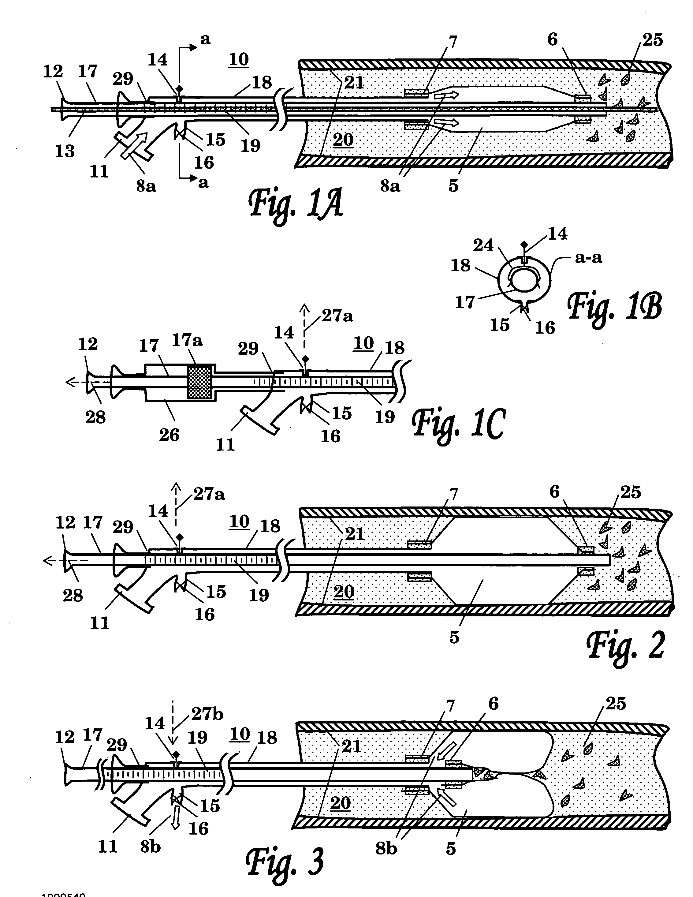
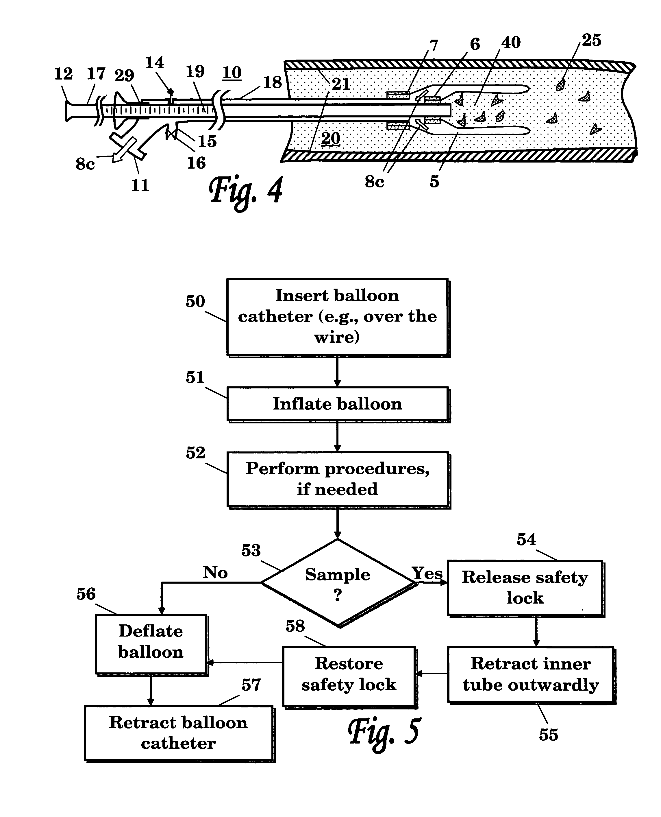
[0020] The present invention is therefore primarily directed to a balloon catheter system comprising at least one inner conduit and one outer conduit mutually disposed one inside the other, such that their longitudinal axes either coincide or are substantially parallel to each other, said inner tube being movably disposed along a longitudinal (i.e. distal-proximal) axis wherein an inflatable element such as a balloon is attached between the distal regions of said conduits, the distal end of the balloon being attached to the distal region of the inner conduit, and the proximal end of the balloon being attached to the distal region of said outer conduit. The catheter system is constructed such that the longitudinal position of the inner conduit in relation to the outer conduit may be altered by means of moving the proximal end of the inner conduit (i.e. the end closest to the operator). In this way, the distal-proximal length of the outer surface of the balloon may be altered, such that the balloon may be caused to progressively move between an elongated, extended conformation and a shortened, terminally-intussuscepted conformation, wherein in the latter conformation, an open-ended inner cavity is created in the terminally-intussuscepted region of the balloon. In use, this inner cavity may be employed to entrap particulate debris, liquids and other objects and substances and safely remove same from the body passage in which the balloon catheter system is inserted. The inflatable element used in the presently-disclosed and described catheter system is of a shape that permits said element to meet the dual requirements of effective debris collection and low-profile delivery and retrieval. Thus, in one preferred embodiment the inflatable element is provided in the form of a balloon having, in its inflated state, a tapered shape with a rounded distal extremity. A further feature of the presently-disclosed system is the presence of means for preventing internal pressure changes that occur as a consequence of changing the length and conformation of the balloon.
[0021] Thus, in one aspect, the present invention provides an OTW balloon catheter system comprising an outer conduit; an inner conduit disposed within the lumen of said outer conduit such that the longitudinal axes of said inner and outer conduits are substantially parallel, and positioned such that the distal tip of said inner conduit extends beyond the distal tip of said outer conduit, wherein said inner conduit is capable of being moved along its longitudinal axis in relation to said outer conduit, and wherein the lumen of said inner conduit is suitable for allowing the passage of a guidewire therethrough; an angioplastic balloon whose proximal margin is attached to the outer surface of the distal tip of said outer conduit, and whose distal margin is attached to the outer surface of the portion of the inner conduit that extends beyond the distal tip of said outer conduit, and wherein the distal portion of said balloon is capable of intussusception upon proximal movement of said inner conduit in relation to said outer conduit; means for the introduction of an expansion fluid into the annular space formed between the inner surface of the outer conduit and the outer surface of the inner conduit and therefrom into the lumen of said balloon, and for the removal thereof, and means for preventing pressure changes within said annular space upon axial movement of said inner conduit in relation to said outer conduit.
[0023] In one preferred embodiment of the present invention, the balloon is characterized by having, in its inflated state, a pre-folding profile, i.e. it has shape which is capable of assisting and guiding the intussusception of the distal portion thereof upon proximal movement of the inner conduit in relation to the outer conduit.
[0040] In one preferred embodiment of the above-defined rapid exchange catheter, the means for permitting unhindered axial movement of the inner conduit is provided by a sealing sleeve that is slidably fitted around the external conduit, such that the angled proximal portion of said inner conduit passes firstly through an elongated aperture in the wall of the external conduit, and secondly through a tightly sealed aperture in said sealing sleeve, such that upon axial movement of the inner conduit, said sealing sleeve is capable of preventing the transfer of fluid through said elongated aperture.
[0051] f) means for preventing pressure changes within said annular space upon axial movement of said inner conduit in relation to said outer conduit; and
[0052] g) means for permitting axial movement of said inner conduit within said outer conduit, such that said movement is not hindered by the passage of the angled proximal part of the inner conduit through said outer conduit.

Problems solved by technology

This arrangement, wherein the guidewire tube is affixed to the catheter's shaft at the location of its lateral port, usually prevents designers from developing new rapid exchange catheter implementations which requires manipulating its inner shaft.
The rapid exchange catheters of the prior art are therefore usually designed for carrying out a particular procedure and their implementations are relatively restricted as a consequence of the need for at least one catheter shaft to exit the catheter system laterally, between the proximal and distal ends of said system.

Method used


Image

  • Balloon catheter
  • Balloon catheter
  • Balloon catheter

Examples


example 1

Finite Element Analysis (FEA) of a Debris-Collecting Balloon for Use in the Present Invention

[0174] FEA is a computerized tool which was used to optimize the balloon design in order to improve its ability to fold in the desired way. The FE model describes an inflated balloon which its edge is retracted, resulting in folding of the balloon. The simulation was performed on different balloon designs and at varied inflation pressures, taking into account the mechanical properties of the balloon material, which was chosen to be nylon 12 or pebax.

[0175] Assumptions:

[0176] i. The balloon is made of a homogenous and isotropic material.

[0177] ii. The balloon's shape is symmetrical around its longitudinal axis.

[0178] iii. The balloon's shape is symmetrical around its mid transverse axis.

[0179] iv. The folding results in flexural stresses in the balloon material. Thus the mechanical properties (Modulus and Poisson Ratio) of the substance when flexed are taken into account in the FE analy...

example 2

Determination of the Force that is Required in Order to Fold the Balloon at Different Inflation Pressure

[0199] Equipment and Materials:

[0200] 3.0 mm Nylon 12 Vestamid L2101F Balloon (Interface Associates 316079-1)

[0201] Glass tube with inner diameter of 3 mm.

[0202] Guidant HI-TORQUE CROSS-IT 200XT 0.014″ Guidewire.

[0203] Hounsfield Test Equipment Model TX0927, 50-N load cell. This computer controlled testing machine enables determining tension, compression, shear, flexure and other mechanical and physical properties of materials. The machine provides selection of test speeds and direction of travel. It can measure the force and displacement values and can also graphically display the test.

[0204] Assouline Compressor type 1.5 HP.

[0205] Fluid dispensing system Model 1500XL.

[0206] Procedure:

[0207] The balloon was inserted into a 3-mm glass tube, at straight position or inclined to 45°. A guidewire was inserted into the inner tube in order to stabilize the folding motion. The b...


PUM


Abstract

A catheter system suitable for the retrieval of debris and other solid or liquid matter from body passages, and the removal of said matter from the body. More particularly, a catheter system including two or more concentrically-arranged conduits and an inflatable element connected therebetween, wherein the inflatable element is arranged such that it may entrap solid or liquid matter in an internal annular cavity.

Description

FIELD OF THE INVENTION [0001] The present invention relates to a catheter system suitable for the retrieval of debris and other solid or liquid matter from body passages, and the removal of said matter from the body. More particularly, the invention relates to catheter systems comprising two or more concentrically-arranged conduits and an inflatable element connected therebetween, wherein said inflatable element is arranged such that it may entrap solid or liquid matter in an internal annular cavity. BACKGROUND OF THE INVENTION [0002] Catheters are used in various interventional procedures for delivering therapeutic means to a treated site (e.g., body organ or passageway such as blood vessels). In many cases, a catheter with a small distal inflatable balloon is guided to the treated site. Once the balloon is in place it is inflated by the operator for affixing it in place, for expanding a blocked vessel, for placing treatment means (e.g., stent) and / or for delivering surgical tools ...

Claims


Application Information

Patent Timeline
Patent Type & Authority Applications(United States)
IPC IPC(8): A61M29/00A61F2/958
CPCA61M25/0119A61M25/1006A61M25/104A61M2025/109A61M2025/1015A61M2025/1068A61M2025/0183A61M25/10A61M25/00
Inventor HIRSZOWICZ, ERANDUBI, SHAY
Owner ANGIOSLIDE
Learn More