Power unit with auxiliary machine driving transmission mechanism

a transmission mechanism and power unit technology, applied in valve drives, machines/engines, gearing, etc., can solve problems such as chain vibration, and achieve the effect of suppressing the vibration of the endless transmission belt effectively, and reducing the vibration of the endless transmission bel

Inactive Publication Date: 2007-04-12
HONDA MOTOR CO LTD
View PDF10 Cites 7 Cited by
  • Summary
  • Abstract
  • Description
  • Claims
  • Application Information

AI Technical Summary

Benefits of technology

[0020] According to the first aspect of the present invention, the following effect is brought about. Since the center distance between the crank shaft and the output shaft can be shortened, the power unit can be made compact in a direction of alignment of the crank shaft and output shaft. Since the first guide can suppress vibration of the endless transmission belt extensively, it can suppress vibration of the endless transmission belt effectively, without deterioration in the working efficiency in the assembly or maintenance of the power unit.
[0021] According to the second aspect of the present invention, the following effect is brought about. Since the fitting part, the rigidity of which is increased by the fastener, is adjacent to the wind-in part of the drive sprocket, the first guide effectively prevents the endless transmission belt from skipping gear teeth. Also, though the fitting part is adjacent to the wind-in part of the drive sprocket, it does not affect the strength of the bearing of the input shaft.
[0022] According to the third aspect of the present invention, the following effect is brought about. Since the second guide can be adjacent to the driven sprocket without increasing the size of the lower crankcase, the second guide can suppress vibration of the endless transmission belt and prevent it from skipping gear teeth effectively.
[0023] According to the fourth aspect of the present invention, the following effect is brought about. In addition to the required rigidity, the first guide can be lightweight and the effect of damping vibration of the endless transmission belt can be improved.
[0024] According to the fifth aspect of the present invention, the following effect is brought about. Since a special member for fitting the first guide is not needed, the structure for fitting the first guide is not complicated and the power unit can be lightweight. Furthermore, since the first guide can be placed in a space which becomes available by placement of the clutch, placement of the first guide no longer makes it necessary to increase the size of the power unit.
[0025] According to the sixth aspect of the present invention, the following effect is brought about. Since the hook type engaging part prevents the effect of suppressing vibration of the endless transmission belt from declining and can be easily engaged with the part to be engaged when the guide is fitted to the upper crankcase, the working efficiency in fitting the guide is improved.

Problems solved by technology

However, in the case that in order to reduce the longitudinal length of the power unit, composed of an internal combustion engine and a transmission, for the sake of compactness by compact longitudinal arrangement of the internal combustion engine and transmission, the center distance between the crank shaft and the counter shaft is shortened by placing the main shaft above and away from the separating plane, the distance between the drive sprocket on the main shaft and the oil pump located below the separating plane increases, which might cause vibration of the chain.

Method used


Image

  • Power unit with auxiliary machine driving transmission mechanism
  • Power unit with auxiliary machine driving transmission mechanism
  • Power unit with auxiliary machine driving transmission mechanism

Examples


Embodiment Construction

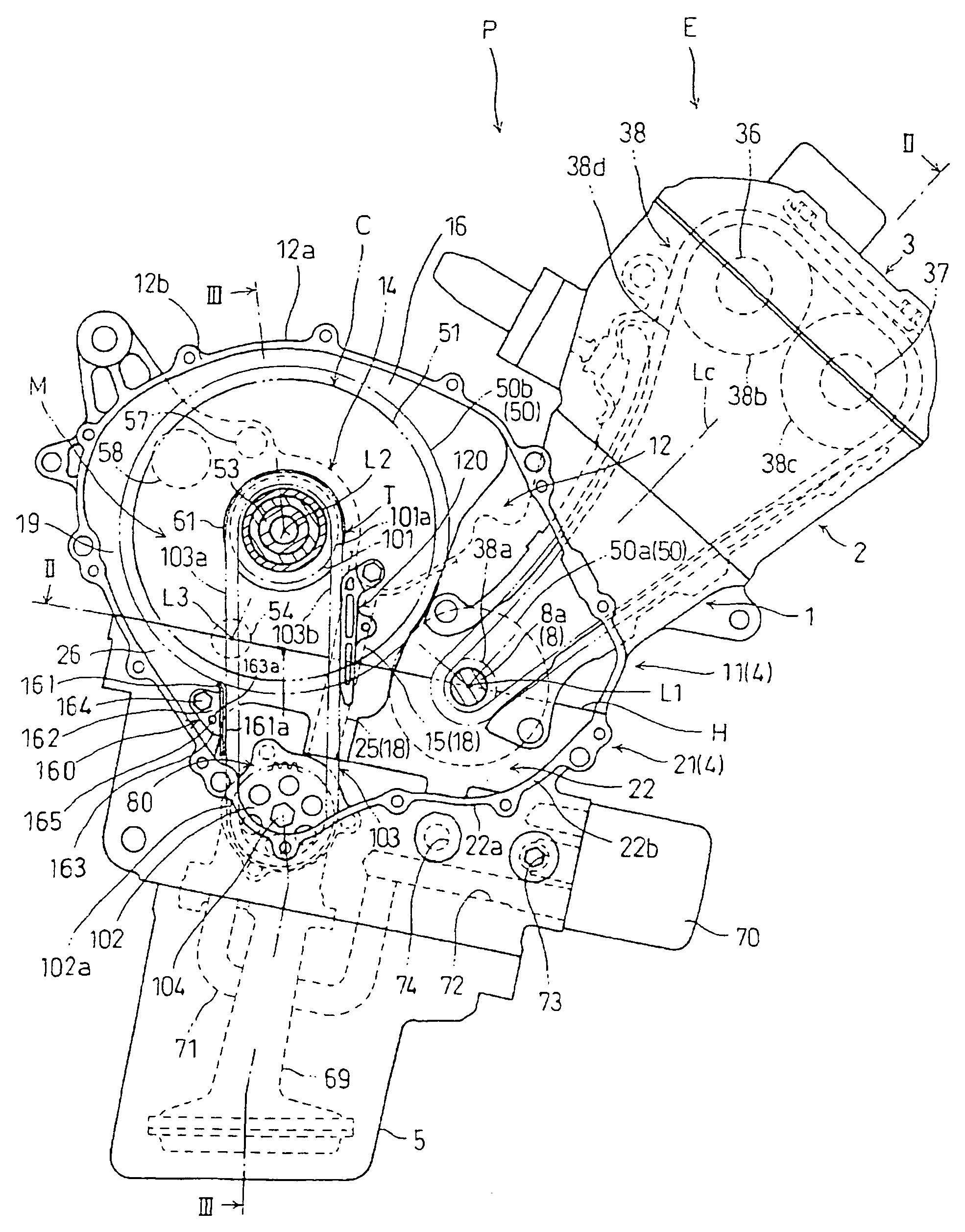
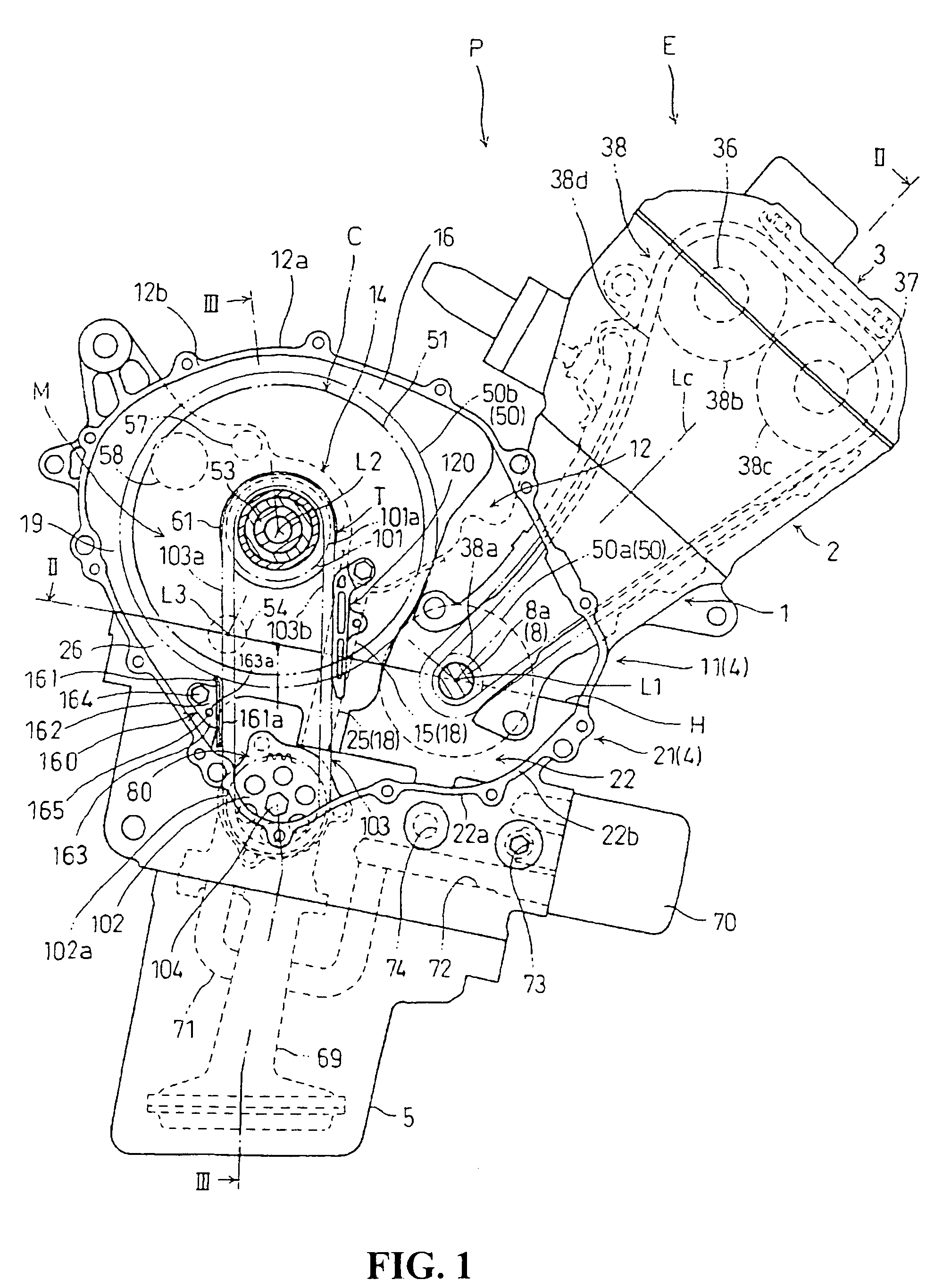
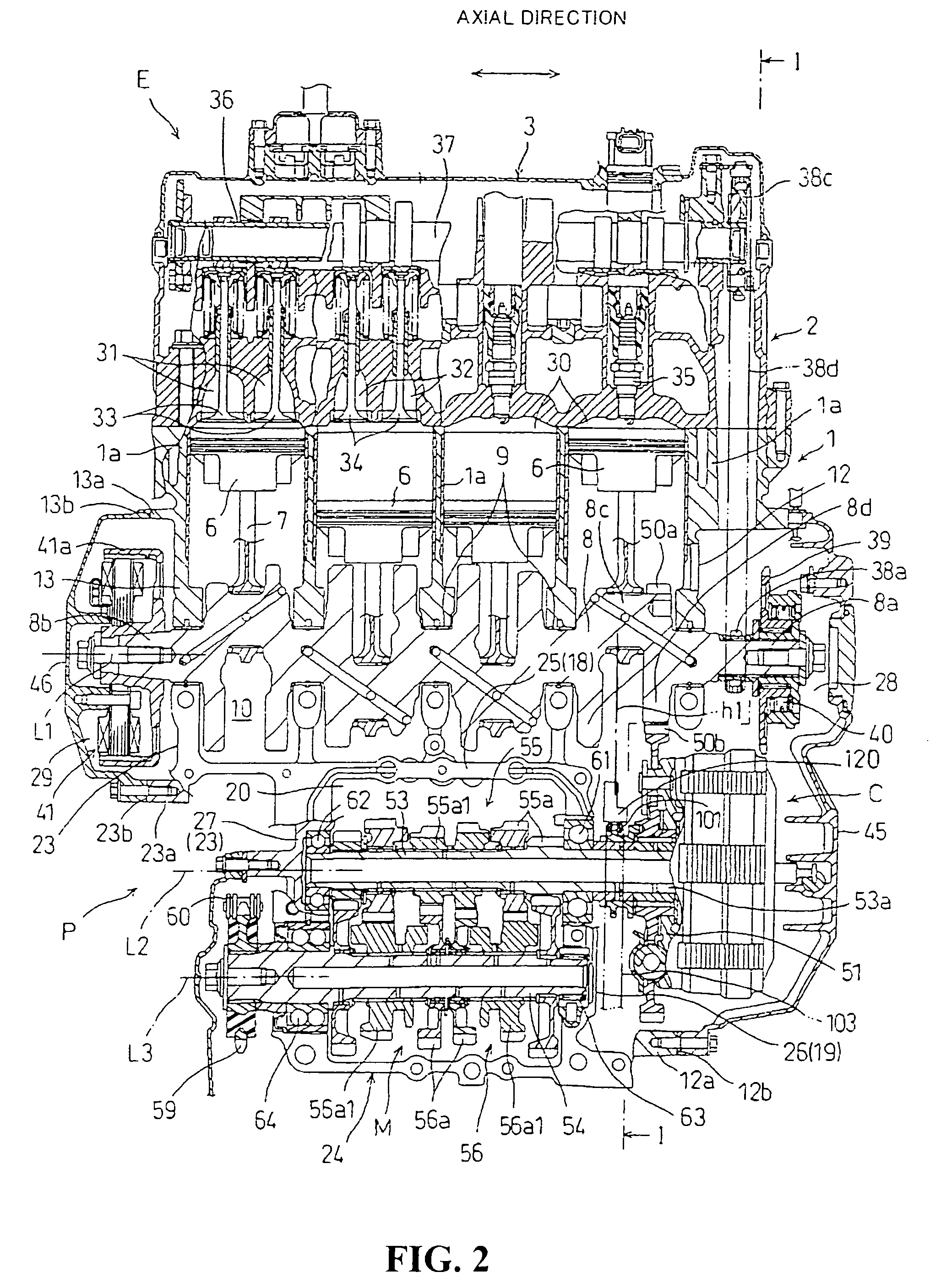
[0032] Referring to FIGS. 1 and 2, a power unit P to which the present invention is applied is to be mounted on a motorcycle as a vehicle and includes a water-cooled multicylinder 4-stroke internal combustion engine E, a multiple-disc friction clutch C as a clutch constituting a power transmission mechanism which transmits power generated by the internal combustion engine E to a rear wheel as a driving wheel, and a constant-mesh type gear transmission M as a transmission.

[0033] The internal combustion engine E, which is to be mounted on a motorcycle with a rotational centerline L1 of a crank shaft 8 transversely oriented and horizontal, has an engine body which includes: a cylinder block 1 as an integral molding of four cylinders la arranged serially, a cylinder head 2 joined to the top end of the cylinder block 1, a head cover 3 joined to the top end of the cylinder head 2, a lower crankcase 21 joined to the bottom end of the cylinder block 1, and an oil pan 5 joined to the bottom...


PUM


Abstract

In a power unit, a counter shaft of a transmission and a crank shaft of an internal combustion engine, both located below a main shaft of the transmission, are arranged parallel to each other on a separating plane H of a crankcase. In a transmission mechanism T which drives an oil pump located below the separating plane H, a drive sprocket is placed on the main shaft of the transmission and a driven sprocket is placed on a drive shaft of the oil pump. An endless chain slidably touches a slender long chain guide along the running direction of the endless chain. The chain guide is fitted only to an end wall of an upper crankcase at its fitting part. The chain guide stretches across the end wall of the upper crankcase and an end wall of a lower crankcase, and effectively suppresses vibration of the endless chain.

Description

CROSS-REFERENCE TO RELATED APPLICATION [0001] The present application claims priority under 35 U.S.C. §119 to Japanese Patent Application No. 2005-285800, filed Sep. 30, 2005, the entire contents of which are hereby incorporated by reference. BACKGROUND OF THE INVENTION [0002] 1. Field of the Invention [0003] The present invention relates to a power unit having an internal combustion engine and a transmission and more particularly to an auxiliary machine driving transmission mechanism having an endless transmission belt wound around a drive sprocket and a driven sprocket to drive an auxiliary machine for the internal combustion engine. [0004] 2. Description of Background Art [0005] As an example of an auxiliary machine driving transmission mechanism which drives an auxiliary machine for an internal combustion engine, one that has been disclosed in JP-A No. 2002-235548 (FIG. 6) has been known. The disclosed transmission mechanism includes a drive sprocket on the main shaft of a trans...

Claims


Application Information

Patent Timeline
Patent Type & Authority Applications(United States)
IPC IPC(8): F16H7/08F16H7/18
CPCF16H7/18
Inventor TAWARADA, YUICHI
Owner HONDA MOTOR CO LTD
Why Eureka
Try Eureka