
Coalescing filtration medium and process

a technology of filtration medium and filtration medium, which is applied in the direction of gravity filter, filtration separation, separation process, etc., can solve the problems of gas streams used in compressors or vacuum pumps, and refrigerants used in refrigeration or air conditioning compressors can become contaminated with liquid aerosols, oil and water

Inactive Publication Date: 2007-04-05
EI DU PONT DE NEMOURS & CO
View PDF19 Cites 110 Cited by
  • Summary
  • Abstract
  • Description
  • Claims
  • Application Information

AI Technical Summary

Benefits of technology

[0008] In a first embodiment, the present invention is directed to a coalescing filtration medium for removing liquid aerosols, oil and/or water from a gas stream comprising a nanofiber web of at least one nanof

Problems solved by technology

Gas streams used in compressors or vacuum pumps and refrigerants used in refrigeration or air conditioning compressors can become contaminated with liquid aerosols, oil and water.

Method used


Image

  • Coalescing filtration medium and process

Examples


example 1

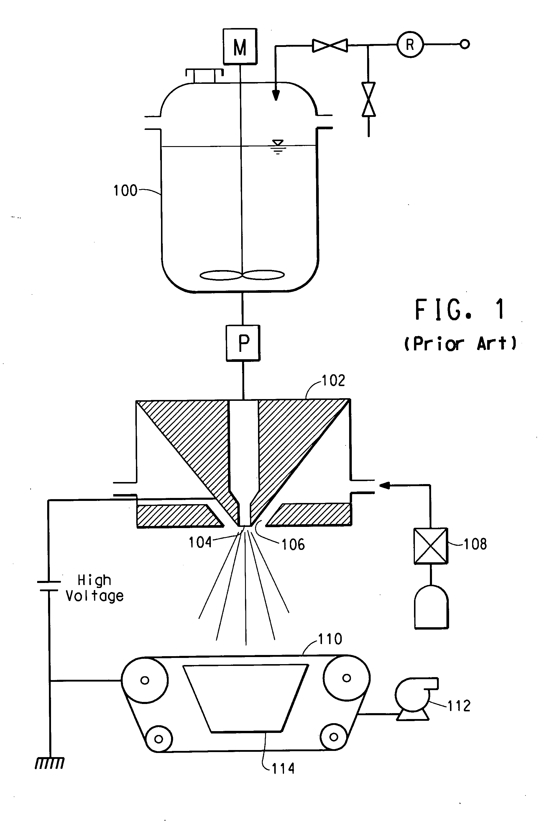
[0039] A nanofiber web of a single nanofiber layer was made. The pack was at room temperature of 24° C. with the pressure of the solution in the spinning nozzles at 11 bar. Compressed air at a temperature of 60° C. was injected through the gas injection nozzles from the spin pack at a rate of 5.5 m3 / min and a pressure of 320 mm H2O. The fibers formed were laid down 330 mm below the exit of the pack onto a porous collector belt moving at 7.38 m / minute. A vacuum chamber beneath the belt assisted in the laydown of the fibers into a single nanofiber layer which comprised the nanofiber web. The nanofiber web properties are summarized in the Table.

example 2

[0040] Example 2 was prepared similarly to Example 1, except the speed of the porous collector belt was increased to 14.78 m / minute. This produced a nanofiber layer of about half of the basis weight of Example 1. The resulting nanofiber layer was placed on the porous collector belt and passed through the electroblowing process to collect another nanofiber layer. This process was repeated until 5 nanofiber layers were collected into one heavy nanofiber web of Example 2. As each additional nanofiber layer was added, the vacuum of the vacuum chamber was increased.

[0041] Alternatively, this example could have been made from one pass through the electroblowing process by decreasing the porous collector belt appropriately. The nanofiber web properties are summarized in the Table.

example 3

[0042] Example 3 was prepared similarly to Example 1, except addition nanofiber layers were added similar to Example 2. A total of 4 nanofiber layers were collected. The nanofiber web properties are summarized in the Table.


PUM

PropertyMeasurementUnit
Lengthaaaaaaaaaa
Fractionaaaaaaaaaa
Thicknessaaaaaaaaaa

Abstract

A coalescing filtration medium is disclosed for removing liquid aerosols, oil and / or water from a gas stream. The medium contains a nanofiber web of at least one nanofiber layer of continuous, substantially polyolefin-free, polymeric nanofibers, each nanofiber layer having an average fiber diameter less than about 800 nm and having a basis weight of at least about 2.5 g / m2.

Description

BACKGROUND OF THE INVENTION [0001] 1. Field of the Invention [0002] The present invention relates to a coalescing filtration medium, specifically a filtration medium for removing liquid aerosols, oil or water from compressed air or gas streams. [0003] 2. Background of the Invention [0004] Gas streams used in compressors or vacuum pumps and refrigerants used in refrigeration or air conditioning compressors can become contaminated with liquid aerosols, oil and water. A filtration apparatus can be used to remove the contaminant. The contaminant is collected on a coalescing filtration medium used in the filtration apparatus. The coalescing filtration medium can be made from woven on nonwoven materials. Such materials are comprised of dense mats of cellulose, glass or synthetic fibers. In order to be efficient, the coalescing filtration medium must trap the contaminant while allowing the gas stream to flow through the filter media with as little impedance or pressure drop as possible all...

Claims


Application Information

Patent Timeline
IPC IPC(8): B01D46/00D04H1/728D04H3/016D04H3/16
CPCB01D39/1623B32B5/022B32B5/06B32B5/26B32B7/08B32B2307/73B32B2262/0261B32B2307/718B32B2307/724B32B2307/728B32B2262/02B01D2239/025B82Y30/00
Inventor JONES, DAVID CHARLESLIM, HYUN SUNG
Owner EI DU PONT DE NEMOURS & CO
Learn More