
Structure of ventilating insole

Inactive Publication Date: 2007-04-05
LIN CHUNG JEN
View PDF23 Cites 132 Cited by
  • Summary
  • Abstract
  • Description
  • Claims
  • Application Information

AI Technical Summary

Benefits of technology

[0009] Therefore, air can enter into the interior of the shoe when walking and shoe can keep ventilating properly.
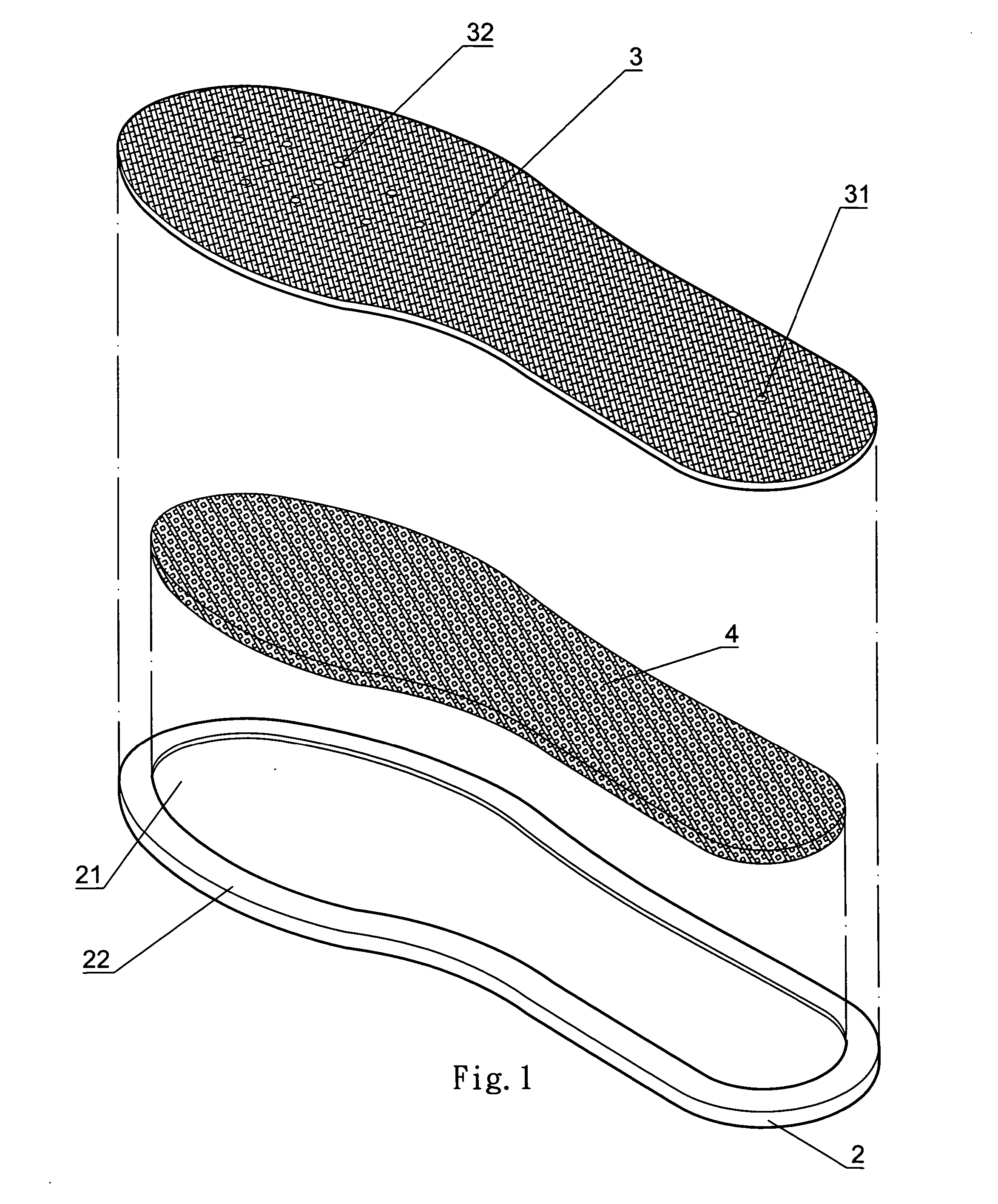
[0010] A second object of this invention is to provide an improved structure of ventilating insole, wherein structure of this invention is very simple without any other supporting parts such as one-way valve and air duct, insole itself is an air chamber, such insole is light and thin with large air contents, so, it can not only exhaust more air while walking, but also be comfortable to wear.
[0011] A third object of this invention is to provide an improved structure of ventilating insole; wherein the lower insole of this invention is molded in one-body-type, so, it saves manpower and material, and further reduces production cost accordingly.
[0012] A fourth object of this invention is to provide an improved structure of ventilating insole; wherein sponge is set under air permeable layer so that it is easy to breath and suck up moisture, contact part between the sole of the foot and air permeable layer may produce air convection due to movement of steps, air inlet ports and air outlet ports are respectively set at the heel and toe portions, therefore, cool air around the heel of the foot can enter into the toe portion of the foot, while the wearer is walking, so that humid and hot air in interior of the shoe are easier to be exhausted.

Problems solved by technology

Usually, in the warmer and more humid climates, shoes often ventilate insufficiently so that heat and sweat produced while walking are not easy to get rid of.
If wearing shoes for a long time, the wearer might feel uncomfortable.
However, such kinds of air chamber are not large enough, so, air content is limited.
Air chamber of this type of ventilating insole only occupies partial space of the insole, so, its air content is less; because the air chamber sets air inlet ports at the rear edge of the heel portion, so, when the wearer is walking, if air inlet ports is not covered by heel, the air in air chamber cannot effectively enter into the toes of the foot.
Furthermore, the air chamber and the support around air chamber are produced separately with spongy material in different densities, since insoles have different sizes, so, it may increase difficulty to assemble such ventilating insoles.

Method used


Image

  • Structure of ventilating insole
  • Structure of ventilating insole
  • Structure of ventilating insole

Examples


Embodiment Construction

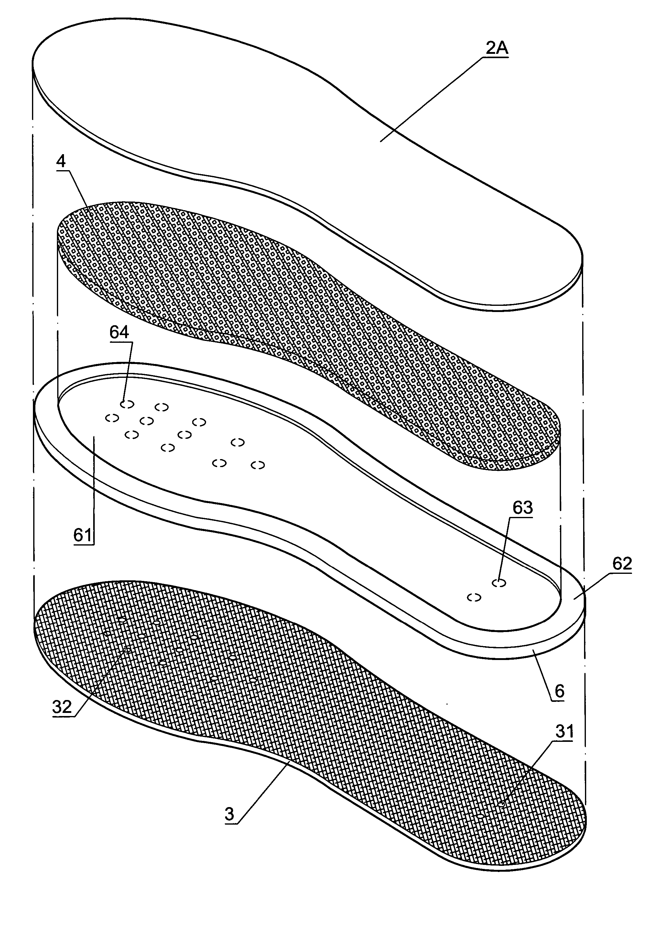
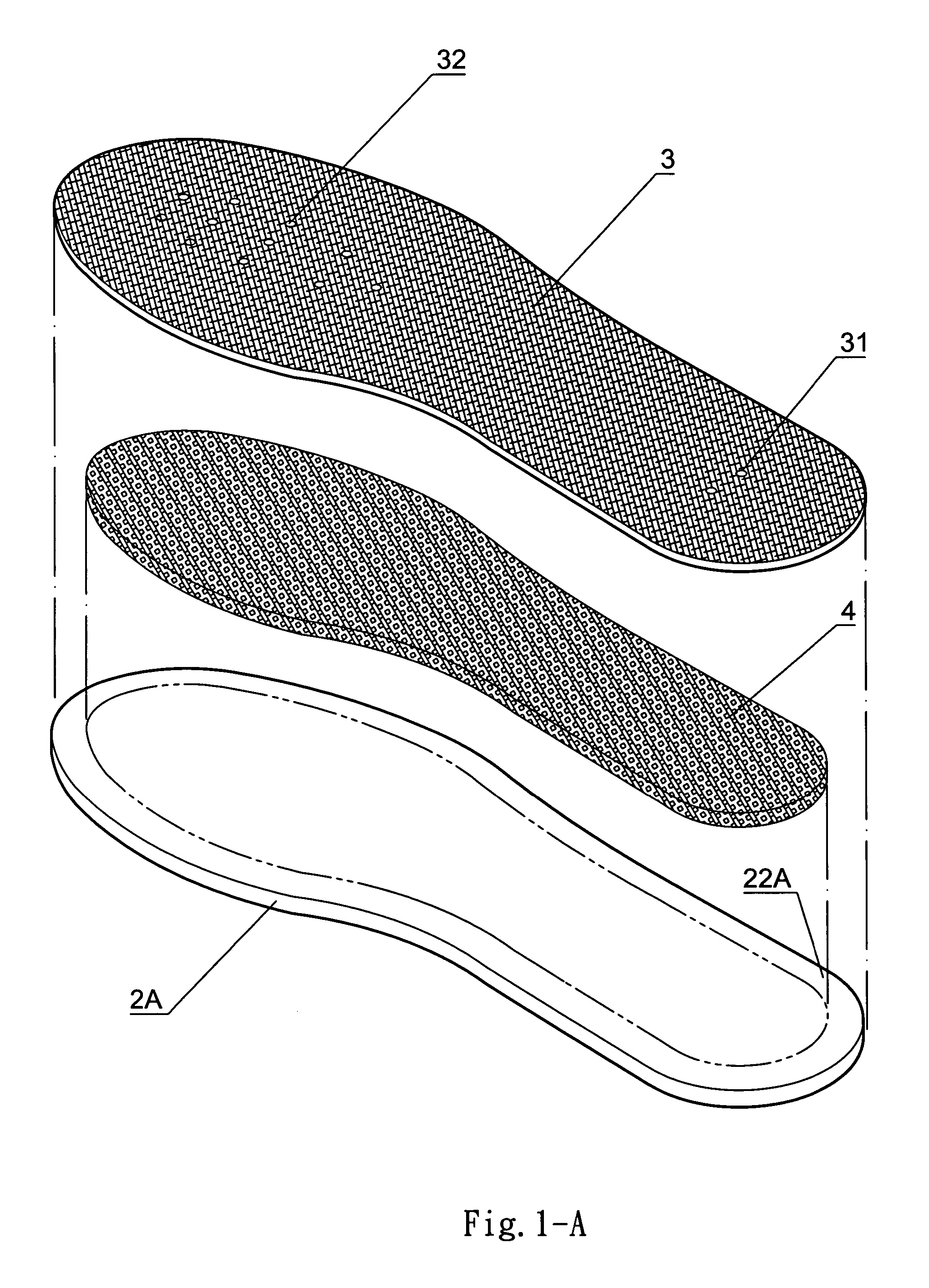
[0022] We hereby specially describe structure and the preferred embodiments of this invention with examples and drawings in the following. First of all, please refer to FIG. 1, FIG. 1-A, FIG. 2 and FIG. 3, this invention is composed of one-body-type insole with one concave trough 21 at central part as lower insole 2, casing 22 is set around trough 21, elastic, porous sponge 4 with same shape of trough 21 is placed onto trough 21, the sponge 4 is elastic and porous, which can be made of different materials. Then casing 22 around trough 21 is glued to air permeable layer 3 (cloth or leather) with a plurality of air inlet ports 31 at the heel portion P1 and a plurality of air outlet ports 32 at the toe portion P2, so as to form an air chamber S of ventilating insole between the air permeable layer 3 and the lower insole 2.

[0023] Please refer to FIG. 1-A for the similar combination in above section, wherein lower insole 2A is not set a trough, a sponge 4 in a shape smaller than the low...


PUM


Abstract

An improved structure of ventilating insole, which is composed of a shoe-shaped lower insole, an air permeable layer (cloth or leather) in shoe-shaped and a sponge is placed between the lower insole and the air permeable layer, its features are as follows, a concave trough with casing is set in the central part of the lower insole when molding it in one-body-type, an elastic, porous sponge which is trough-shaped in equal thickness is placed onto the trough of the lower insole, then casing around trough is glued to the air permeable layer with air inlet ports at the heel and air outlet ports at the toe portions, a ventilating insole is then finished. Such an insole provides for pumping cool air into the interior of the shoe as a result of the normal walking action, thus, the shoe can keep ventilating properly.

Description

BACKGROUND OF THE INVENTION [0001] 1) Field of the Invention [0002] The present invention relates to an improved structure of ventilating insole, which is a concave trough with casing is set in the central part of the lower insole, then place a sponge which is trough-shaped in equal thickness and made of elastic and porous materials onto the trough of the lower insole, the casing around trough is glued to an air permeable layer, so that an air chamber can be formed owing to elasticity of sponge, and air permeable layer are respectively set a plurality of air inlet ports at the heel portion and a plurality of air outlet ports at the toe portion, a ventilating insole is then finished. [0003] Such a ventilating insole provides for pumping cool air into the interior of the shoe as a result of the normal walking action, thus, the shoe keep ventilating properly. [0004] 2) Description of the Prior Art [0005] Usually, in the warmer and more humid climates, shoes often ventilate insufficient...

Claims


Application Information

Patent Timeline
IPC IPC(8): A43B7/06A43B13/38
CPCA43B17/08A43B7/06A43B13/38
Inventor LIN, CHUNG-JEN
Owner LIN CHUNG JEN
Learn More