
System and method for providing trigger information in a video signal and playing out a triggered event

a video signal and trigger information technology, applied in the field of system and method for providing trigger information in a video signal and playing out a trigger event, can solve the problems of extreme cost and time-consuming ordeal

Inactive Publication Date: 2007-03-29
FORSTER DARREN P +1
View PDF1 Cites 22 Cited by
  • Summary
  • Abstract
  • Description
  • Claims
  • Application Information

AI Technical Summary

Problems solved by technology

However, because of the distribution mechanism employed by networks and cable operators, some issues arise.
While a number of mechanisms can be employed to solve this problem, most would require extensive modification or rewiring of existing equipment, which can be an extremely expensive and time consuming ordeal.

Method used


Image

  • System and method for providing trigger information in a video signal and playing out a triggered event
  • System and method for providing trigger information in a video signal and playing out a triggered event
  • System and method for providing trigger information in a video signal and playing out a triggered event

Examples


Embodiment Construction

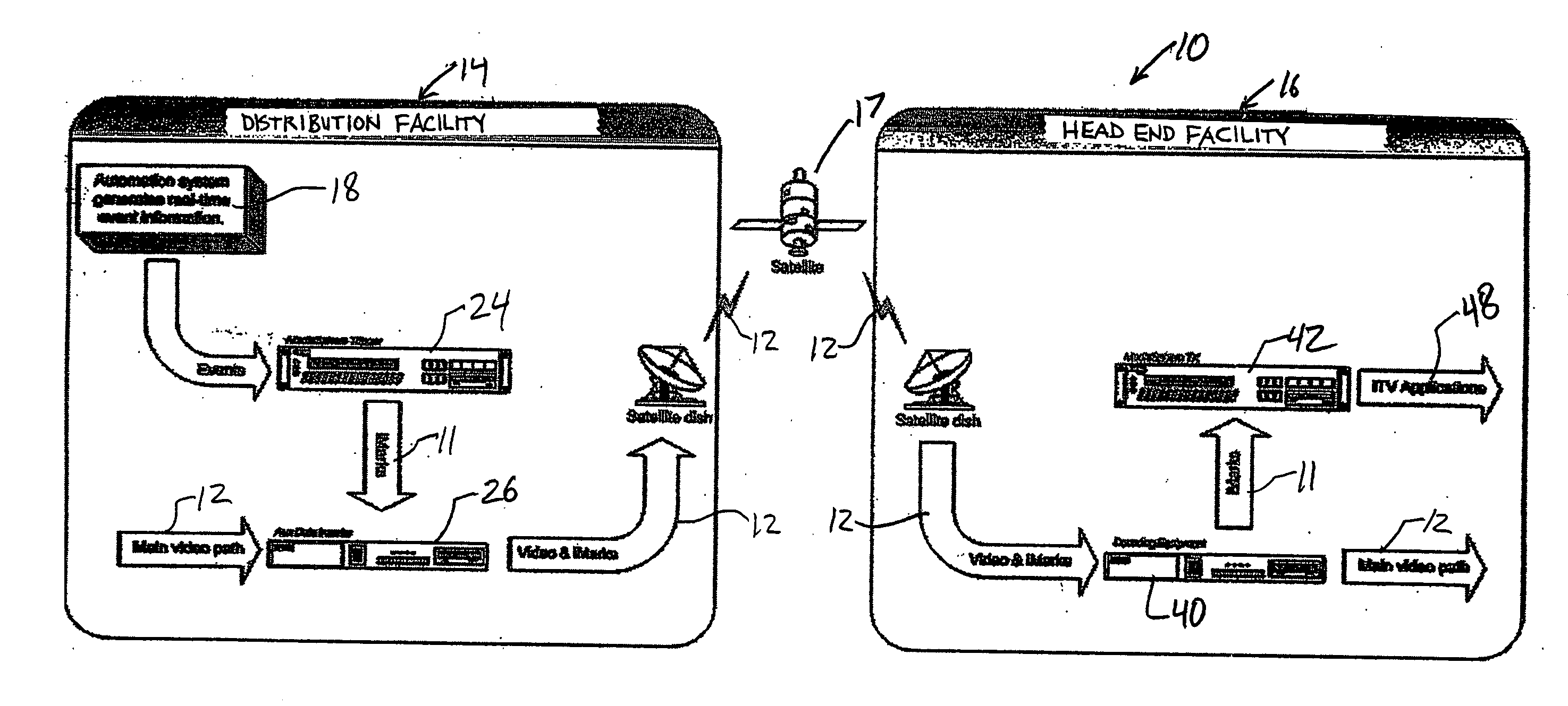
[0017]FIG. 1 depicts an example of a system 10 for providing trigger information 11 in a video signal 12 and playing out a triggered event in response to the trigger information 11. The system 10 includes a distribution facility 14, which may be operated by a television (TV) network, and one or more head-end facilities 16, which may be operated by TV stations, cable TV service providers, satellite TV service providers, or the like. The distribution facility 14 and head-end facility 16 send and receive the video signal 12 by a satellite communications link or other suitable communications link 17. As will be described in further detail hereinafter, the system 10 uses a portion of the Vertical Blanking Interval (VBI) of the video signal 12 (e.g., the Extended Data Services (XDS) auxiliary data channels) to transmit trigger information (iMarks) 11 from the distribution facility 14 to each head-end facility 16. XDS is an American standard classified under Electronic Industries Alliance ...


PUM


Abstract

A system for providing trigger information in a video signal and outputting a triggered event comprises a distribution facility and at least one head-end facility. The distribution facility includes an automation system, a trigger unit, and a data inserter. The automation system controls video and audio sources to play out the program events to provide a video signal, and outputs the event identifier when the associated program event is played out. The trigger unit outputs a trigger identifier associated with the event identifier. The data inserter inserts the trigger identifier in a portion of a vertical blanking interval of the video signal. The head-end facility includes a decoder and a content server. The decoder detects the trigger identifier in the portion of the vertical blanking interval of the video signal. The content server plays out the triggered event.

Description

CROSS REFERENCE TO RELATED APPLICATION(S) [0001] This application claims the benefit of U.S. Provisional Application No. 60 / 721,336, filed Sep. 27, 2005, which is incorporated by reference as if disclosed herein in its entirety.COPYRIGHT NOTICE [0002] A portion of the disclosure of this patent document contains material which is subject to copyright protection. The copyright owner has no objection to the facsimile reproduction by anyone of the patent document or the patent disclosure, as it appears in the U.S. Patent and Trademark Office patent files or records, but otherwise reserves all copyright whatsoever. BACKGROUND [0003] Over the course of half a century, the television industry has seen many startling advances. One such recent advance is the advent of interactive television (iTV). From video on demand and on-screen program guides (EPGs) to the ability to book your next holiday right from your remote control, iTV promises a more encompassing and streamlined television experie...

Claims


Application Information

Patent Timeline
Patent Type & Authority Applications(United States)
IPC IPC(8): G06F11/00
CPCH04N21/2221H04N21/235H04N21/8545H04N21/47202H04N21/435
Inventor FORSTER, DARREN P.PEMBERTON, SAMUEL W. D.
Owner FORSTER DARREN P
Learn More