Storage system and setting method for storage configuration information
a storage system and information technology, applied in the field of storage system and setting method for storage configuration information, can solve the problems of difficult and time-consuming operation of setting or changing storage configuration information via a network, and the difficulty of setting and changing storage configuration information is difficult and time-consuming operation, so as to achieve the effect of smoothly setting storage configuration information
- Summary
- Abstract
- Description
- Claims
- Application Information
AI Technical Summary
Benefits of technology
Problems solved by technology
Method used
Image
Examples
first embodiment
[First Embodiment]
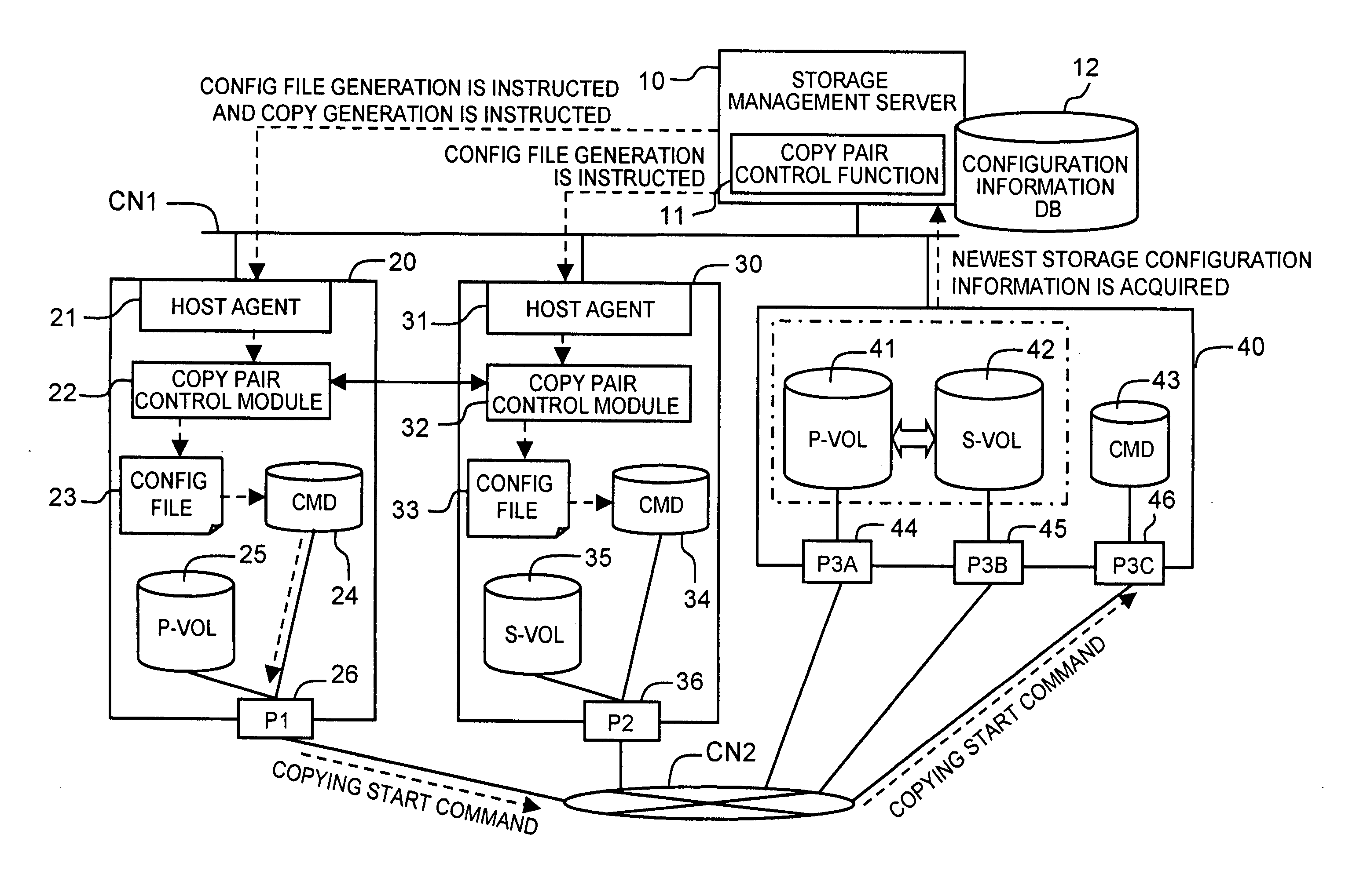
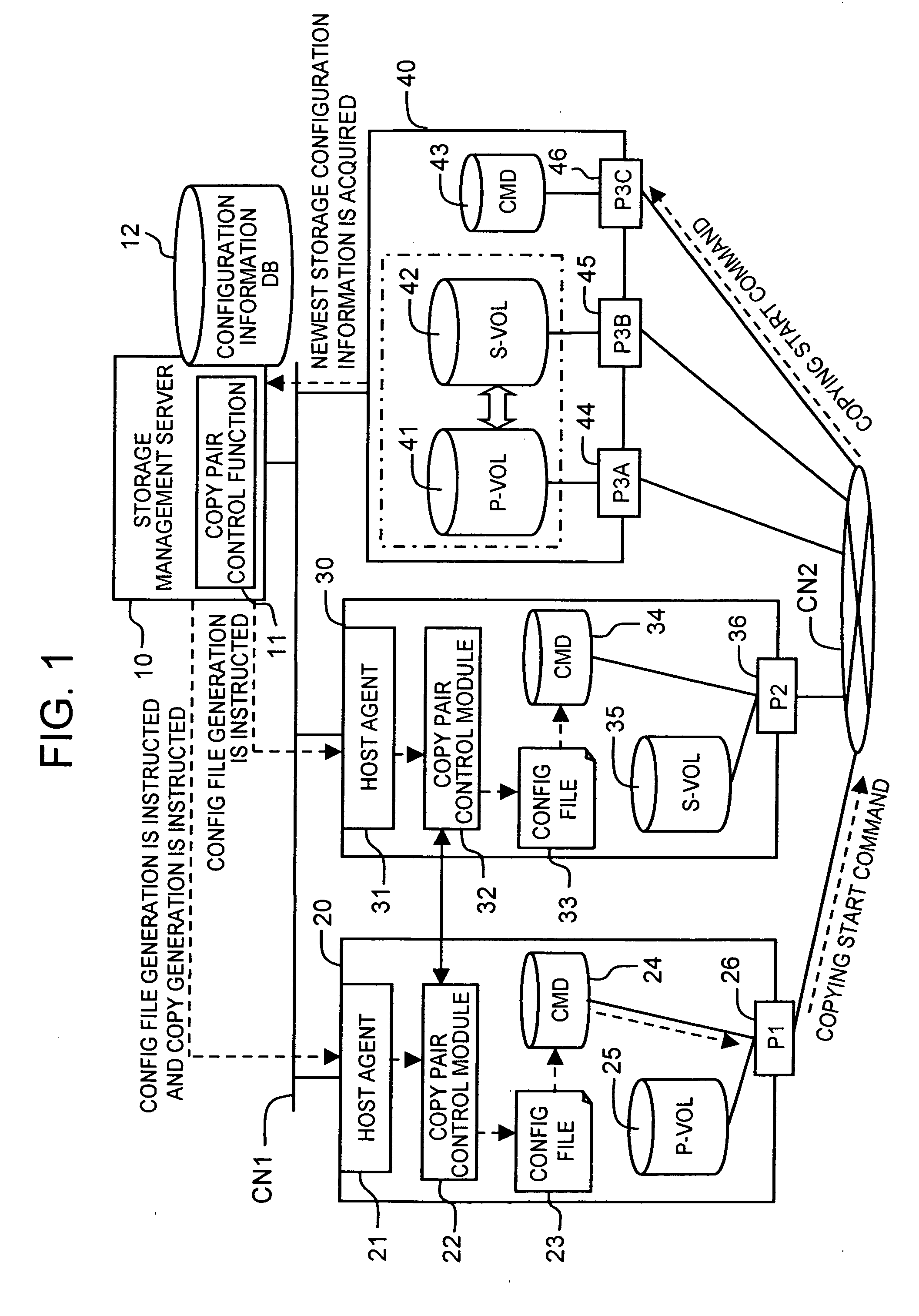
[0048] The first embodiment of the present invention will be described below based on FIGS. 1 through 7. FIG. 1 is a block diagram showing the outline of the entire storage system of the present embodiment.
[0049] The storage system comprises a storage management server 10, a plurality of host computers 20, 30, a storage subsystem 40, and a first communication network CN1 and a second communication network CN2 for connecting those devices, each of the aforesaid components being described hereinbelow.
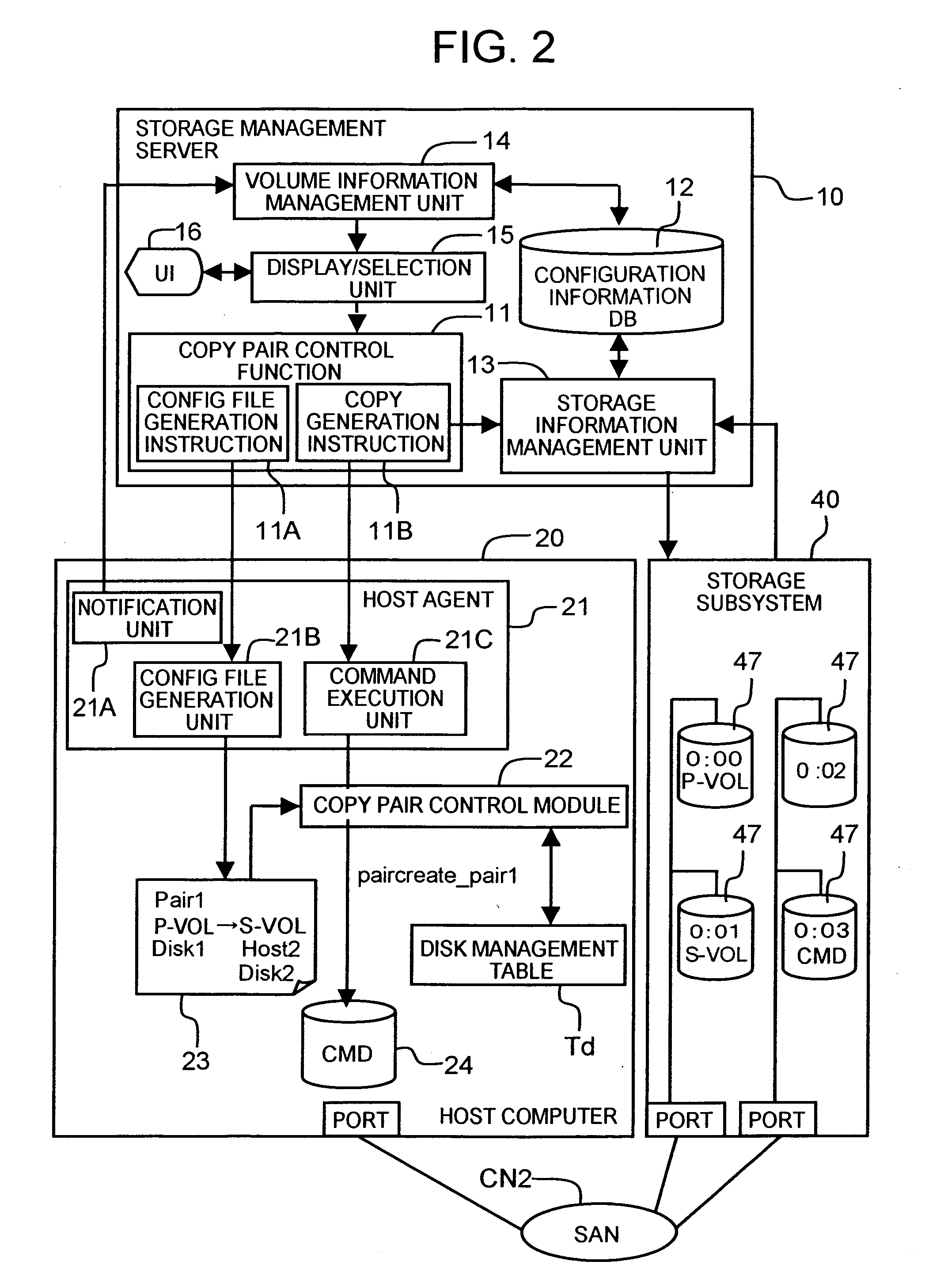
[0050] The storage management server (abbreviated hereinbelow as “a management server”) 10 serves for managing the storage subsystem 40. The management server 10 comprises a copy pair control function 11 and a configuration information database (abbreviated hereinbelow as DB) 12. The management server 10 instructs the generation of a configuration setting file (shown as a “config file” in the figures) to the host computers 20, 30 and instructs the host computer 20, in ...
second embodiment
[Second Embodiment]
[0083] The second embodiment of the present invention will be explained hereinbelow with reference to FIGS. 8 through 11. The specific feature of the present embodiment is that the notification of the copying start instruction has been optimized.
[0084]FIG. 8 shows the outline of the entire storage system of the present embodiment. For example, three host computers 50, 60, 70 are provided in the storage subsystem of the present embodiment. The host computers 50, 60, 70 comprise the respective host agents 51, 61, 71, copy pair control modules 52, 62, 72, configuration setting files 53, 63, 73, control devices 54, 64, 74, and volumes. The first host computer 50 comprises a primary volume 55. The second host computer 60 comprises a secondary volume 65 forming a pair with the primary volume 55 of the first host computer 50 and the other primary volume 66. The third host computer 70 has a secondary volume 75 forming a pair with the primary volume 66 of the second host ...
third embodiment
[Third Embodiment]
[0095]FIG. 12 is a block diagram showing the outline of the entire storage system of the third embodiment of the present invention. A specific feature of the present embodiment is the application to the case in which copy pairs are formed by a plurality of storage subsystems.
[0096] The storage subsystem of the present embodiment comprises a first storage subsystem 90 and a second storage subsystem 100. The first storage subsystem 90 provides a primary volume 91 to the first host computer 20. The second storage subsystem 100 provides a secondary volume 101 to the second host computer 30. The storage subsystems 90, 100 comprises respective control devices 92, 102. The primary volume 91 of the first storage subsystem 90 and the secondary volume 101 of the second storage subsystem 100 form a copy pair.
[0097] A copy command from the host computer 20 is transmitted to the control devices 92, 102 of respective storage subsystems 90, 100. Furthermore, if the copying betw...
PUM
 Abstract
Description
Claims
Application Information
 - R&D
- Intellectual Property
- Life Sciences
- Materials
- Tech Scout
- Unparalleled Data Quality
- Higher Quality Content
- 60% Fewer Hallucinations
Browse by: Latest US Patents, China's latest patents, Technical Efficacy Thesaurus, Application Domain, Technology Topic, Popular Technical Reports.
© 2025 PatSnap. All rights reserved.Legal|Privacy policy|Modern Slavery Act Transparency Statement|Sitemap|About US| Contact US: help@patsnap.com


