
Control of pulse duty cycle based upon footswitch displacement

a technology of pulse duty cycle and footswitch, which is applied in the field of control of pulse duty cycle based upon footswitch displacement, can solve the problems of unfavorable fluidic surge, damage inflicted on patients, and complex control of handheld surgical instruments for phaco surgery

Inactive Publication Date: 2007-03-29
JOHNSON & JOHNSON SURGICAL VISION INC
View PDF99 Cites 68 Cited by
  • Summary
  • Abstract
  • Description
  • Claims
  • Application Information

AI Technical Summary

Benefits of technology

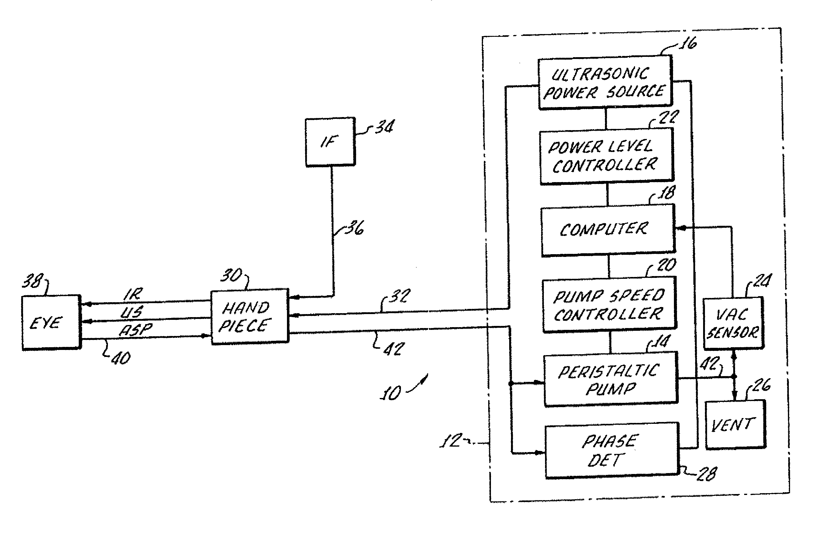
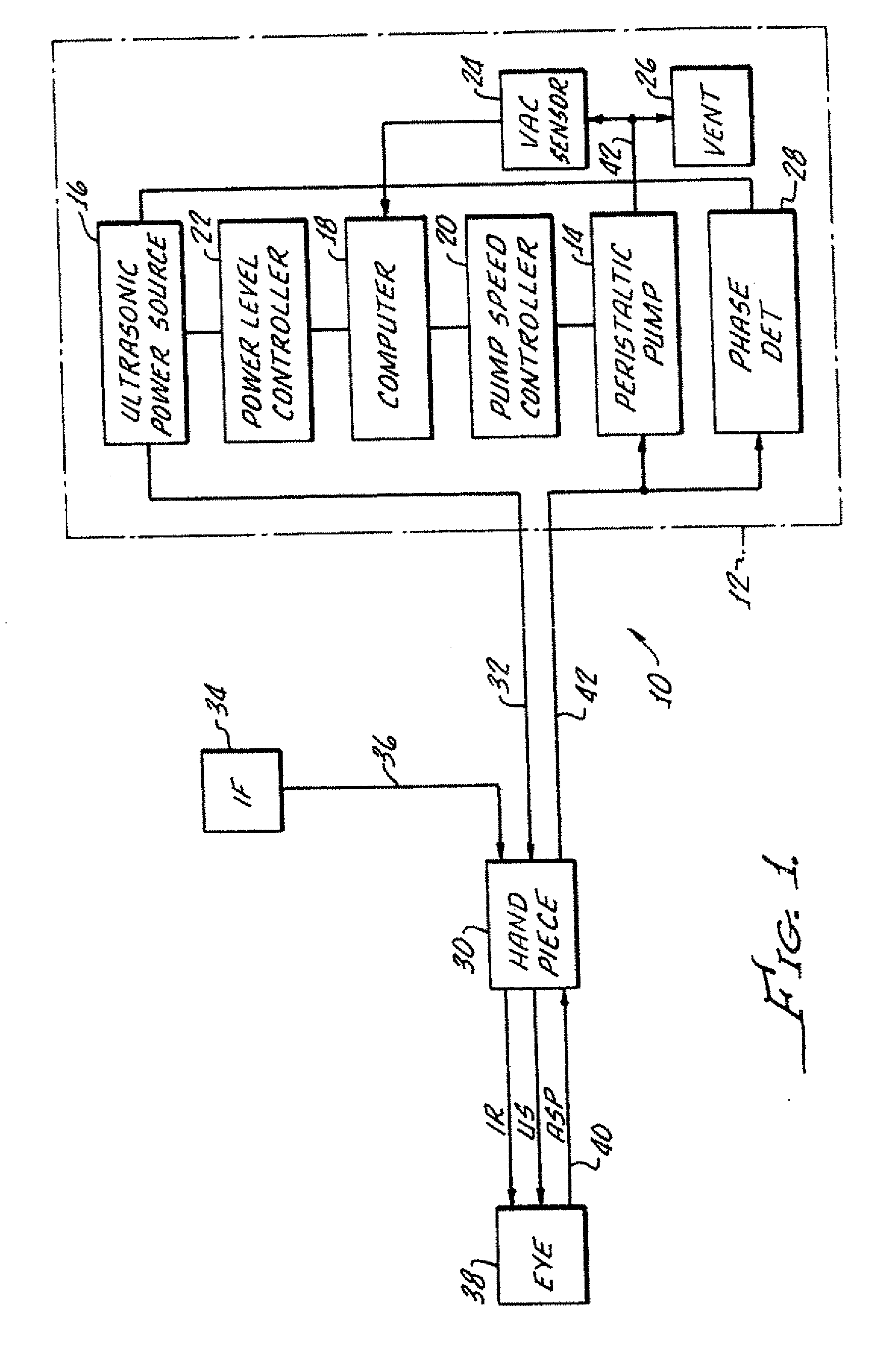
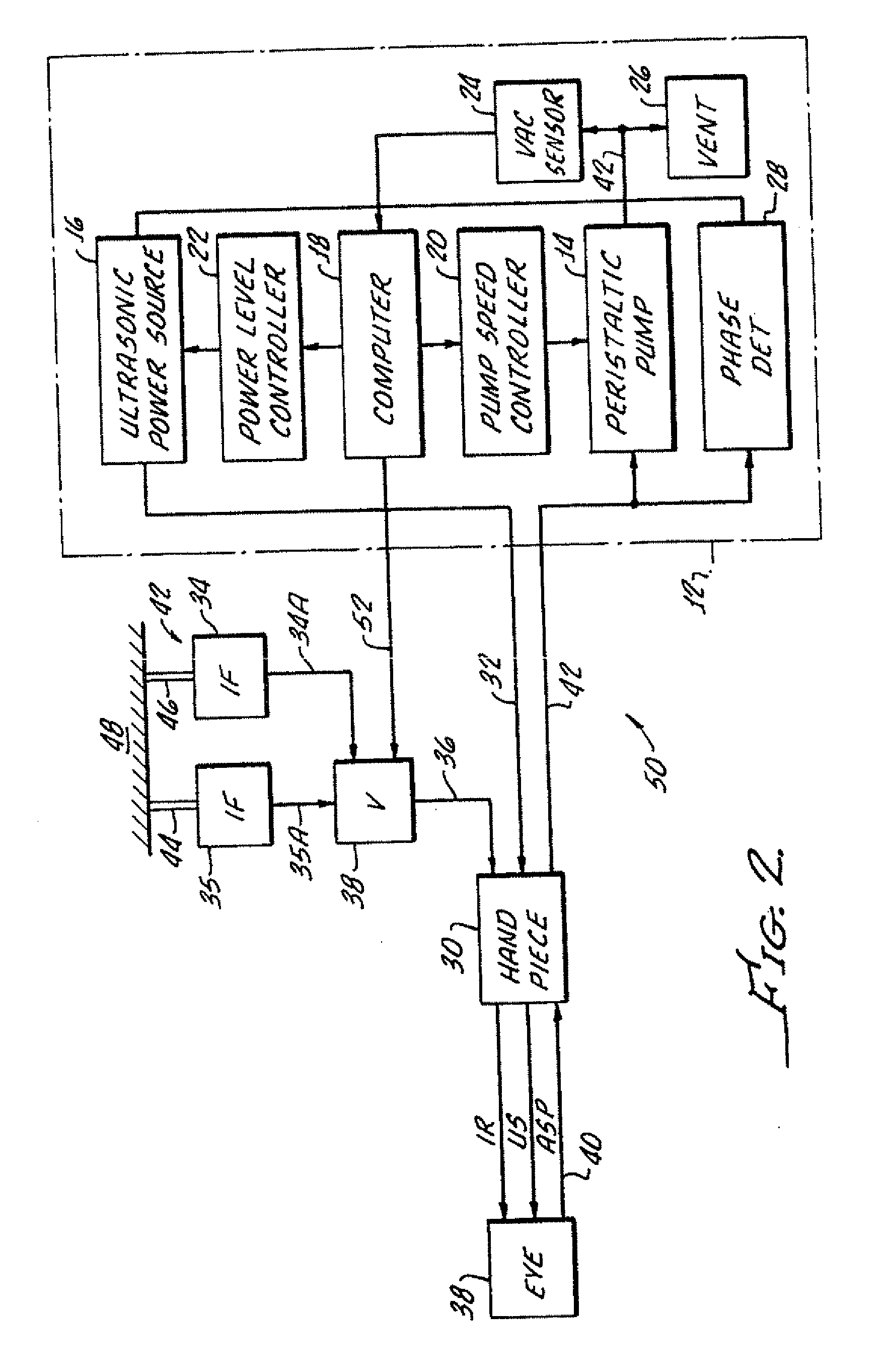
[0006] Many surgical instruments and controls in use today linearly control the vacuum or linearly control the flow of aspiration fluid. This feature allows the surgeon to precisely “dispense” or control the “speed” at which he / she employs, either the vacuum or the flow, but not both. However, there often are times during surgery when the precise control of at least one of the variables (vacuum, aspiration rate, or ultrasonic power) is desired over another. The experienced user, understanding the relationship between the vacuum and the flow, may manually adjust the preset variable appropriately at the console in order to obtain an acceptable performance. However, if this adjustment is overlooked, then the combination of both high vacuum and high flow can cause undesirable fluidic surges at the surgical site with possible damage inflicted on the patient.
[0028] Interrupted power pulse methods have been developed in order to drive the needle with reduced heating to avoid overheating and burning of tissue. The present invention improves this power pulse method, and allows an operator to modulate involved power settings with a foot pedal switch, inter alia. SUMMARY OF THE INVENTION

Problems solved by technology

However, there often are times during surgery when the precise control of at least one of the variables (vacuum, aspiration rate, or ultrasonic power) is desired over another.
However, if this adjustment is overlooked, then the combination of both high vacuum and high flow can cause undesirable fluidic surges at the surgical site with possible damage inflicted on the patient.
It should be apparent that the control of handheld surgical instruments for use in phaco surgery is complex.
This goal is complicated by the fact that the phase angle of the ultrasonic handpiece is also dependent on the loading of the transducer which occurs through the mechanically resonant system which includes the needle.
That is, contact with the needle with tissue and fluids within the eye create a load on the piezoelectric crystals with concomitant change in the operating phase angle.
However, problems arise in the measurement of the phase shift without dependence on the operating frequency of the phacoemulsification handpiece.

Method used


Image

  • Control of pulse duty cycle based upon footswitch displacement
  • Control of pulse duty cycle based upon footswitch displacement
  • Control of pulse duty cycle based upon footswitch displacement

Examples


example 2-47 khz

OPERATION

[0101] Period of 1 clock cycle—1 / F@47 KHz=21.28×10⁻⁶S [0102] Integrator output for one reference cycle [0103] (150×103 V / S)×(21.28×10⁻⁶S)=3.19 Volts [0104] Integrator output from 90 degree cycle duration [0105] (150×103 V / S)×(5.32×10¹⁰-6S)=0.798 Volts [0106] Resulting Numerical count from A / D converter [0107] =3.19 Volts / 256 counts=0.0124 Volts per count [0108] Actual Number of A / D counts for 90 degrees at 47 KHz [0109] =0.798 / 0.0124=64 counts

[0110] A plot of phase angle as a function of frequency is shown in FIG. 10 for various handpiece 30 loading, a no load (max phase), light load, medium load and heavy load.

[0111] With reference to FIG. 11, representing max phase mode operation, the actual phase is determined and compared to the max phase. If the actual phase is equal to, or greater than, the max phase, normal aspiration function is performed. If the actual phase is less than the max phase, the aspiration rate is changed, with the change being proportionate to the cha...


PUM


Abstract

Phacoemulsification apparatus includes a phacoemulsification handpiece having a needle and an electrical circuitry for ultrasonic vibrating the needle. A power source provides pulsed electrical power to the handpiece electrical circuitry and an input is provided for enabling a surgeon to select an amplitude of dislighted pulses and a pulse width. A control system and pulse duty cycle is provided for controlling the off duty cycle to insure heat dissipation before a subsequent pulse is activated, including a foot pedal switch.

Description

[0001] This application is a continuation of U.S. patent application Ser. No. 10 / 680,595 filed Oct. 6, 2003, which is a continuation-in-part of U.S. patent application Ser. No. 09 / 764,814 filed Jan. 16, 2001, now U.S. Pat. No. 6,629,948, issued Oct. 7, 2003, which is a continuation-in-part of U.S. patent application Ser. No. 09 / 298,669 filed Apr. 23, 1999, now U.S. Pat. No. 6,394,974, issued May 28, 2002, which is a continuation-in-part of U.S. patent application Ser. No. 09 / 206,452 filed Dec. 7, 1998, now abandoned, which is a continuation of U.S. patent application Ser. No. 08 / 787,229, filed Jan. 22, 1997, now U.S. Pat. No. 5,852,794, issued Dec. 22, 1998.[0002] The present invention is generally directed to a method and apparatus for controlling the flow of fluid from a source to a patient and removal of fluids from the patient through a phacoemulsification handpiece as well as controlling power provided to the phacoemulsification handpiece. [0003] The flow of fluid to and from a...

Claims


Application Information

Patent Timeline
Patent Type & Authority Applications(United States)
IPC IPC(8): A61F9/00A61B17/00A61B17/32A61B18/00A61F9/007B06B1/02
CPCA61B17/320068A61B2017/0003A61B2017/00106A61B2017/00194A61B2018/00636B06B2201/76A61F9/007A61F9/00745B06B1/0246B06B1/0253B06B2201/55A61B2018/00666A61B2017/32007A61B2017/00977A61B2017/00973A61B2017/320084A61B2017/0019A61B2017/00185A61B2017/00181
Inventor KADZIAUSKAS, KENNETH E.ROCKLEY, PAUL
Owner JOHNSON & JOHNSON SURGICAL VISION INC
Learn More