
Diaphragm pump

Inactive Publication Date: 2007-03-29
ALPS ALPINE CO LTD
View PDF0 Cites 6 Cited by
  • Summary
  • Abstract
  • Description
  • Claims
  • Application Information

AI Technical Summary

Benefits of technology

[0009] One exemplary object of the present embodiments is to provide a 4-valve diaphragm pump that is liquid tight at the connecting parts of flow channels formed over an upper housing and a lower housing. A second exemplary object of the present embodiments is to provide a 4-valve diaphragm pump capable of ensuring the liquid tightness of a suction flow channel and a discharge flow channel with high reliability and durability.
[0015] By keeping a compressive force in the stacked direction of the upper housing, the diaphragm, and the lower housing from being applied to any of the sealing rings, and allowing a compressive in a direction (radial direction) orthogonal to the stacked direction to be applied to the sealing rings, the liquid tightness can be ensured with high durability.

Problems solved by technology

If the upper housing is composed of two members, a problem occurs in the structure in which the liquid tightness of the suction flow channel and the discharge flow channel is ensured.

Method used


Image

  • Diaphragm pump
  • Diaphragm pump
  • Diaphragm pump

Examples


Embodiment Construction

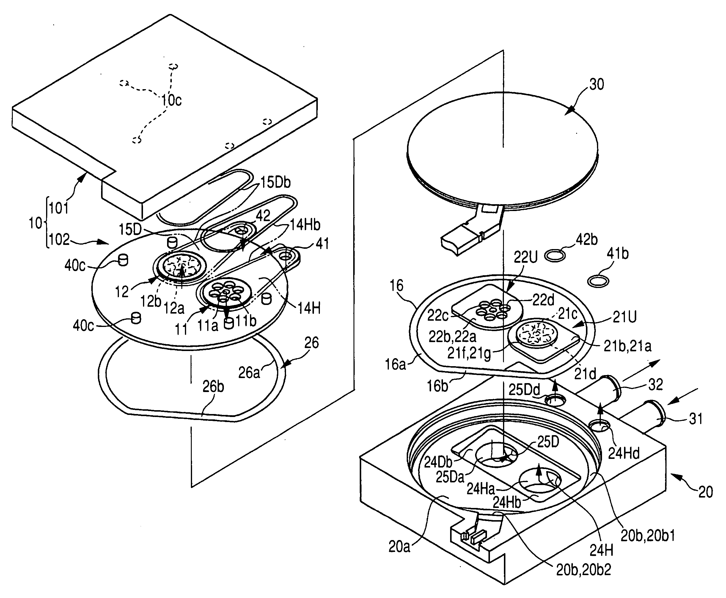
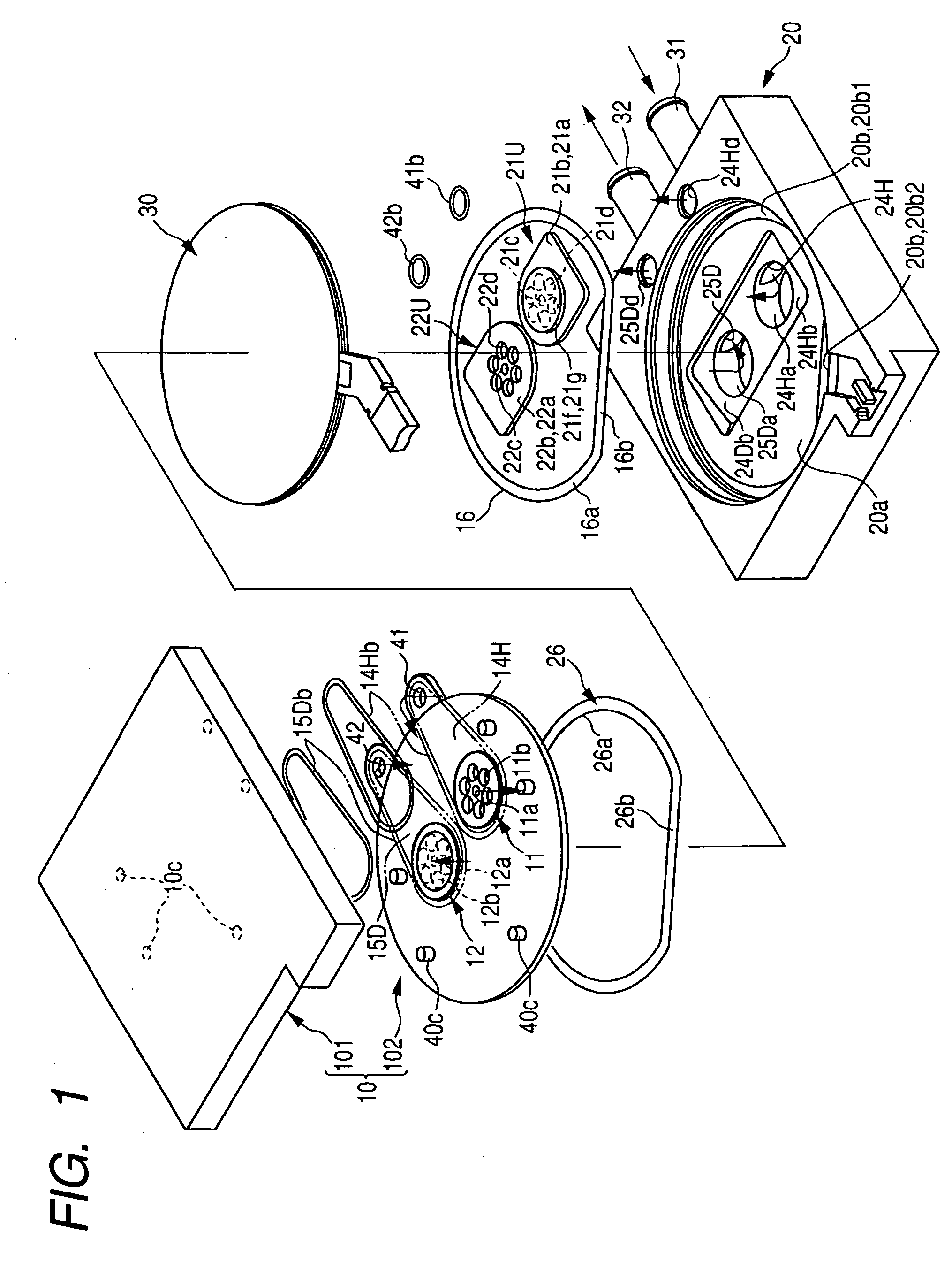
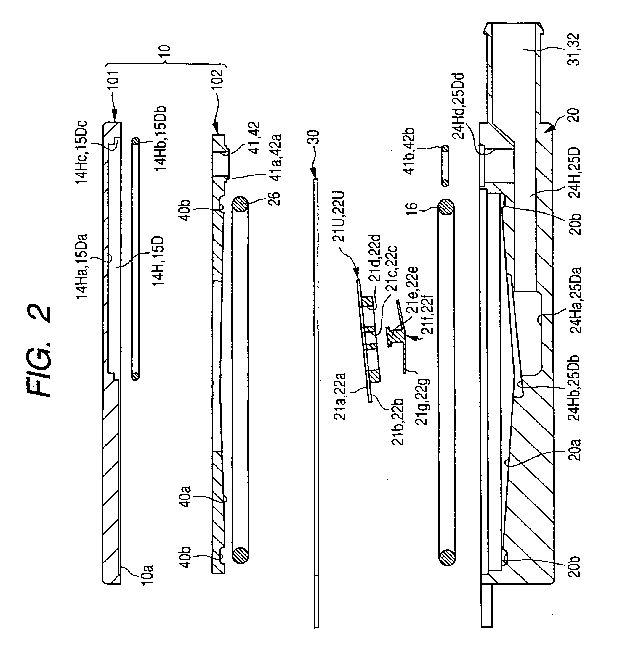
[0033] Illustrated embodiments are obtained by applying the present embodiments to a 4-valve diaphragm pump that the present applicant proposed the principle in Japanese Patent Application No. 2004-154991. One embodiment thereof will be described with reference to FIGS. 1 to 7. In one exemplary embodiment, the diaphragm pump has an upper housing 10, a lower housing 20, and a piezoelectric vibrator 30, and is in the shape of a flat rectangular parallelepiped as a whole. The upper housing 10 is composed of a blind plate 101 and a pump chamber plate 102, and all the blind plate 101, the pump chamber plate 102, and the lower housing 20 are molded articles made of a resin material.

[0034] The lower housing 20 is a member in the shape of a flat rectangular parallelepiped, which is most large-sized and has a complicate shape, among the molded articles. In the lower housing, a recessed part 20a for forming a pump chamber is formed so as to be open to the side opposing the piezoelectric vibr...


PUM


Abstract

A diaphragm pump is provided. The diaphragm includes an upper housing, a diaphragm, and a lower housing. Recessed parts are formed in the surfaces of the upper and lower housings that face the diaphragm to define an upper pump chamber and a lower pump chamber above and below the diaphragm. A suction port and a discharge port are formed in the lower housing to communicate with the lower pump chamber. Branch channels are formed in the lower housing and the upper housing to communicate the suction port and the discharge port with the upper pump chamber. Suction-side check valves are respectively provided between the suction port and the upper pump chamber and between the suction port and the lower pump chamber. Discharge-side check valves are provided between the discharge port and the upper pump chamber and between the discharge port and the lower pump chamber.

Description

[0001] This application claims the benefit of Japanese Patent Application No. 2005-280548 filed on Sep. 27, 2005 and Japanese Patent Application NO. 2006-136693 filed on May 16, 2006. BACKGROUND [0002] 1. Field [0003] The present embodiments relate to a diaphragm pump. [0004] 2. Related Art [0005] A diaphragm pump, as disclosed in, for example, Japanese Unexamined Patent Application Publication No. 11-182413, is configured such that a pump chamber (variable volume chamber) is formed by a diaphragm. A pair of flow channels connected with the pump chamber is provided with a pair of check valves, which are different in the direction of flow (a suction-side check valve, which allows the flow of fluid to the pump chamber, and a discharge-side check valve, which allows the flow of fluid from the pump chamber). When the diaphragm is vibrated, since the volume of the pump chamber changes, and the operation of opening the suction-side check valve during the stroke in which the volume increas...

Claims


Application Information

Patent Timeline
IPC IPC(8): F04B35/00
CPCF04B43/0736F04B43/04
Inventor NAKAJIMA, JIROYAMADA, SATOSHI
Owner ALPS ALPINE CO LTD
Learn More