Superconducting system, superconducting circuit chip, and high-temperature superconducting junction device with a shunt resistor
a superconducting circuit and superconducting circuit technology, applied in the direction of superconductor devices, semiconductor devices, electrical appliances, etc., can solve the problems of insufficient performance of the nb latch interface circuit, inability to drive the semiconductor device directly, and significant increase in hysteresis, so as to achieve sufficient amplification capability
- Summary
- Abstract
- Description
- Claims
- Application Information
AI Technical Summary
Benefits of technology
Problems solved by technology
Method used
Image
Examples
first embodiment
[0052] The first embodiment will be described first.
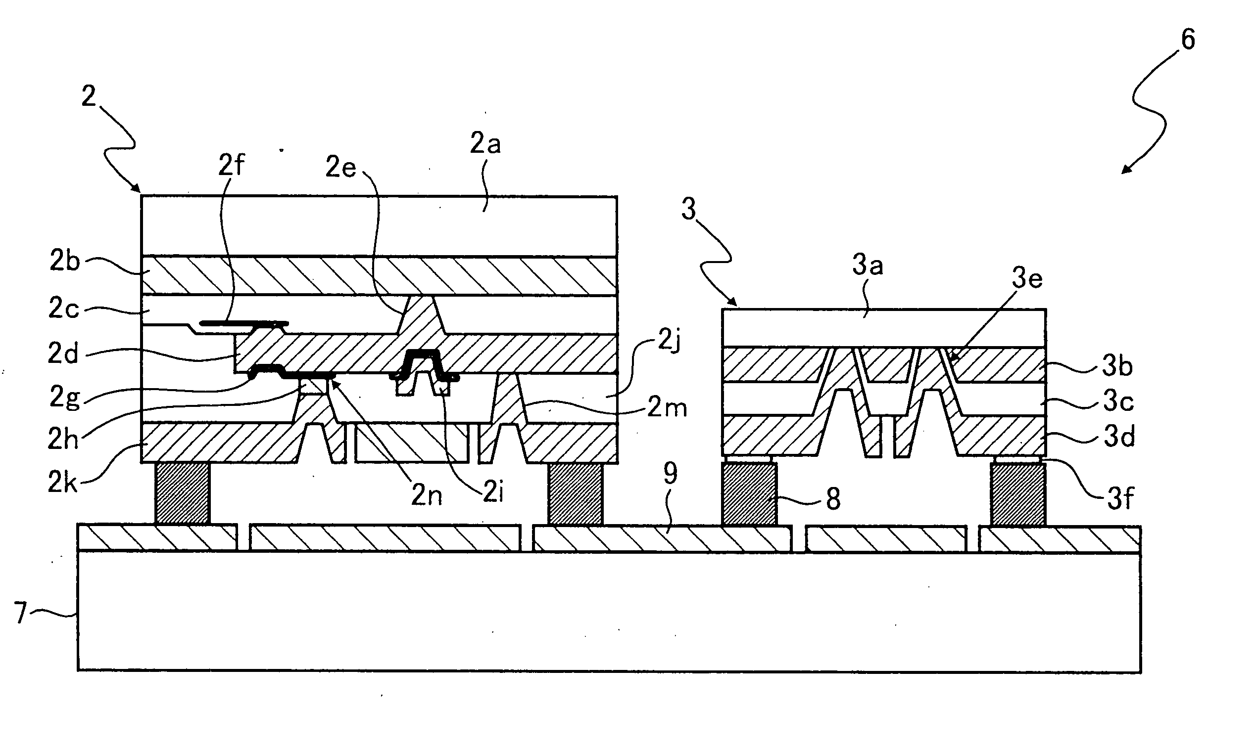
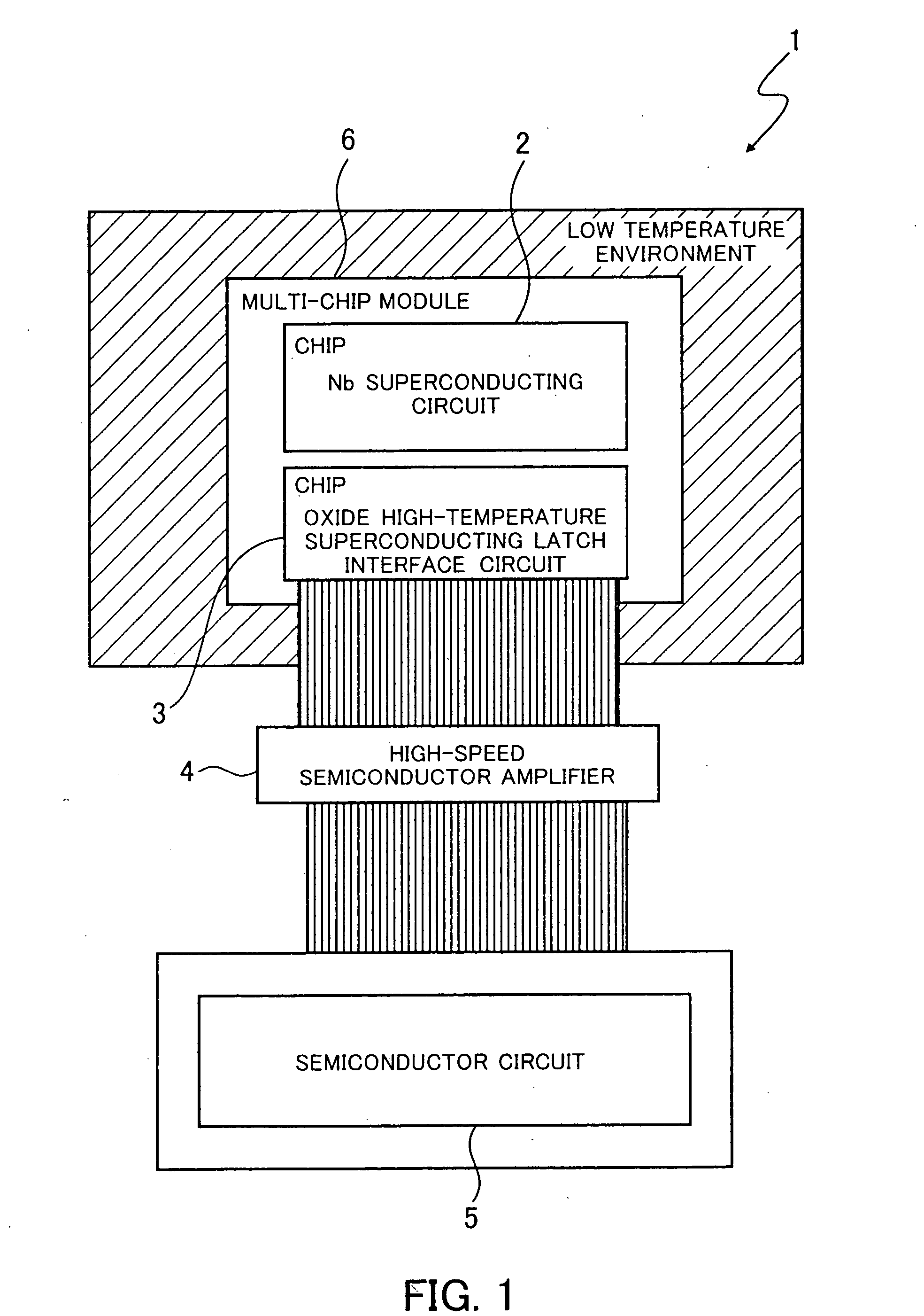
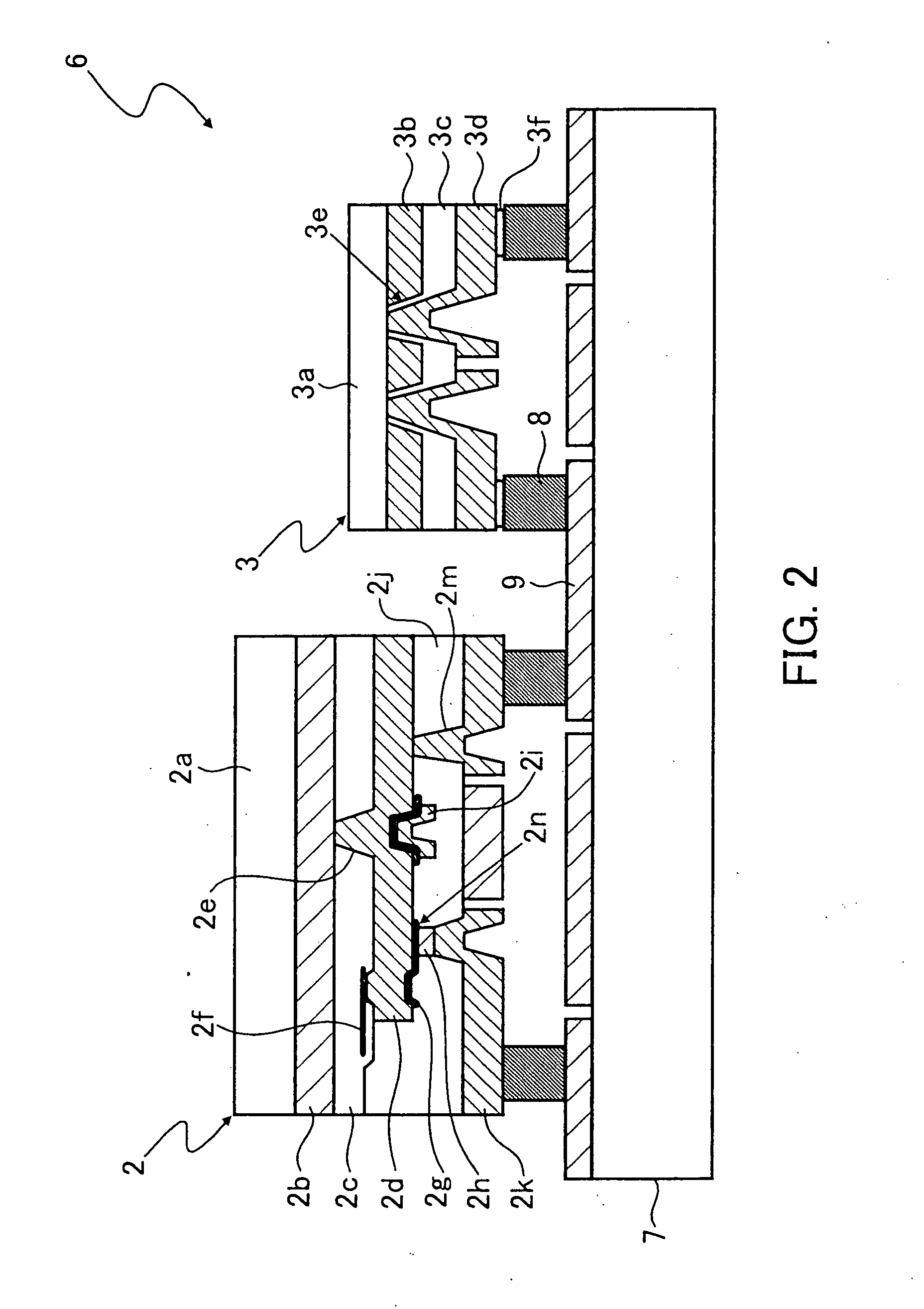
[0053]FIG. 1 shows the structure of a superconducting system according to the first embodiment of the present invention. A superconducting system 1 shown in FIG. 1 comprises an Nb superconducting circuit 2, being a low-temperature superconducting circuit formed by the use of Nb, and an oxide high-temperature superconducting latch interface circuit 3, being a latch driver formed by the use of an oxide high-temperature superconductor. The Nb superconducting circuit 2 is an SFQ circuit having a Josephson junction formed by the use of Nb. The oxide high-temperature superconducting latch interface circuit 3 is an interface circuit having a Josephson junction formed by the use of an oxide high-temperature superconductor having composition, such as YBaCuO, YbBaCuO, DyBaCuO, ErBaCuO, HoBaCuO, or NdBaCuO. The Nb superconducting circuit 2 and the oxide high-temperature superconducting latch interface circuit 3 are in a low temperature enviro...
second embodiment
[0067] The second embodiment will now be described.
[0068]FIG. 3 shows the structure of a superconducting system according to the second embodiment of the present invention. Components in FIG. 3 which are the same as those shown in FIG. 1 are marked with the same symbols and detailed descriptions of them will be omitted.
[0069] A superconducting system 20 according to the second embodiment of the present invention differs from the superconducting system 1 according to the first embodiment of the present invention in that an Nb superconducting circuit 2 and an oxide high-temperature superconducting latch interface circuit 3 are formed on the same substrate, that is to say, in that there is only one superconducting circuit chip 21. The rest of the structure of the superconducting system 20 is the same as that of the superconducting system 1. In addition, the function and effect of the superconducting system 20 are the same as those of the superconducting system 1. That is to say, the c...
third embodiment
[0071] The third embodiment will now be described.
[0072]FIG. 4 shows the structure of a superconducting system according to the third embodiment of the present invention. Components in FIG. 4 which are the same as those shown in FIG. 1 are marked with the same symbols and detailed descriptions of them will be omitted.
[0073] In a superconducting system 30 according to the third embodiment of the present invention, an Nb superconducting circuit 2 and an oxide high-temperature superconducting latch interface circuit 3 are not connected by a wiring, such as a PTL or a JTL. JTLs in both circuits are connected via a superconductive solder bump 31 and these circuits make up a multi-chip module 32. In the superconducting system 30, the Nb superconducting circuit 2 and the oxide high-temperature superconducting latch interface circuit 3 connected by the bump in this way are located in a low temperature environment. The rest of the structure of the superconducting system 30 is the same as th...
PUM
 Abstract
Description
Claims
Application Information
 - R&D
- Intellectual Property
- Life Sciences
- Materials
- Tech Scout
- Unparalleled Data Quality
- Higher Quality Content
- 60% Fewer Hallucinations
Browse by: Latest US Patents, China's latest patents, Technical Efficacy Thesaurus, Application Domain, Technology Topic, Popular Technical Reports.
© 2025 PatSnap. All rights reserved.Legal|Privacy policy|Modern Slavery Act Transparency Statement|Sitemap|About US| Contact US: help@patsnap.com


