Eureka AIR delivers breakthrough ideas for toughest innovation challenges, trusted by R&D personnel around the world.

Treatment of chloraminated water

a chloramine and water treatment technology, applied in water/sewage treatment by oxidation, biocide, application, etc., can solve the problems of chloramines having a propensity to decay, destroying biofilms, and noticeable change in taste and smell of water, so as to restrict microbial growth in water

Inactive Publication Date: 2007-03-22
THE WATER CORP
View PDF12 Cites 0 Cited by
  • Summary
  • Abstract
  • Description
  • Claims
  • Application Information

AI Technical Summary

Benefits of technology

[0014] In accordance with a second aspect of the present invention there is provided a method of substantially eliminating a biofilm formed in bodies of water or vessels or pipes containing bodies of water, characterised in that the method comprises the steps of introducing chlorine, ammonia and copper into the water.

Problems solved by technology

One problem which arises in the use of chloramines in water is that the chloramines have a propensity to decay.
This has the effect of destroying the biofilm.
Several problems are associated with this method.
These include the presence in the newly chlorinated water of an undesirable level of disinfectant by-products, in addition to a noticeable change in the taste and smell of the water.
Should the quantity of added chlorine not be sufficient, it can actually reduce the effective chlorine in the water, resulting in inadequate disinfection.
Further, where water is being reticulated over a long distance, a periodic change from chloramination disinfection to free chlorine disinfection requires the presence of significant treating infrastructure at locations along the distance.
None of these solutions have thus far proved satisfactory.

Method used


Image

  • Treatment of chloraminated water
  • Treatment of chloraminated water
  • Treatment of chloraminated water

Examples


example 1

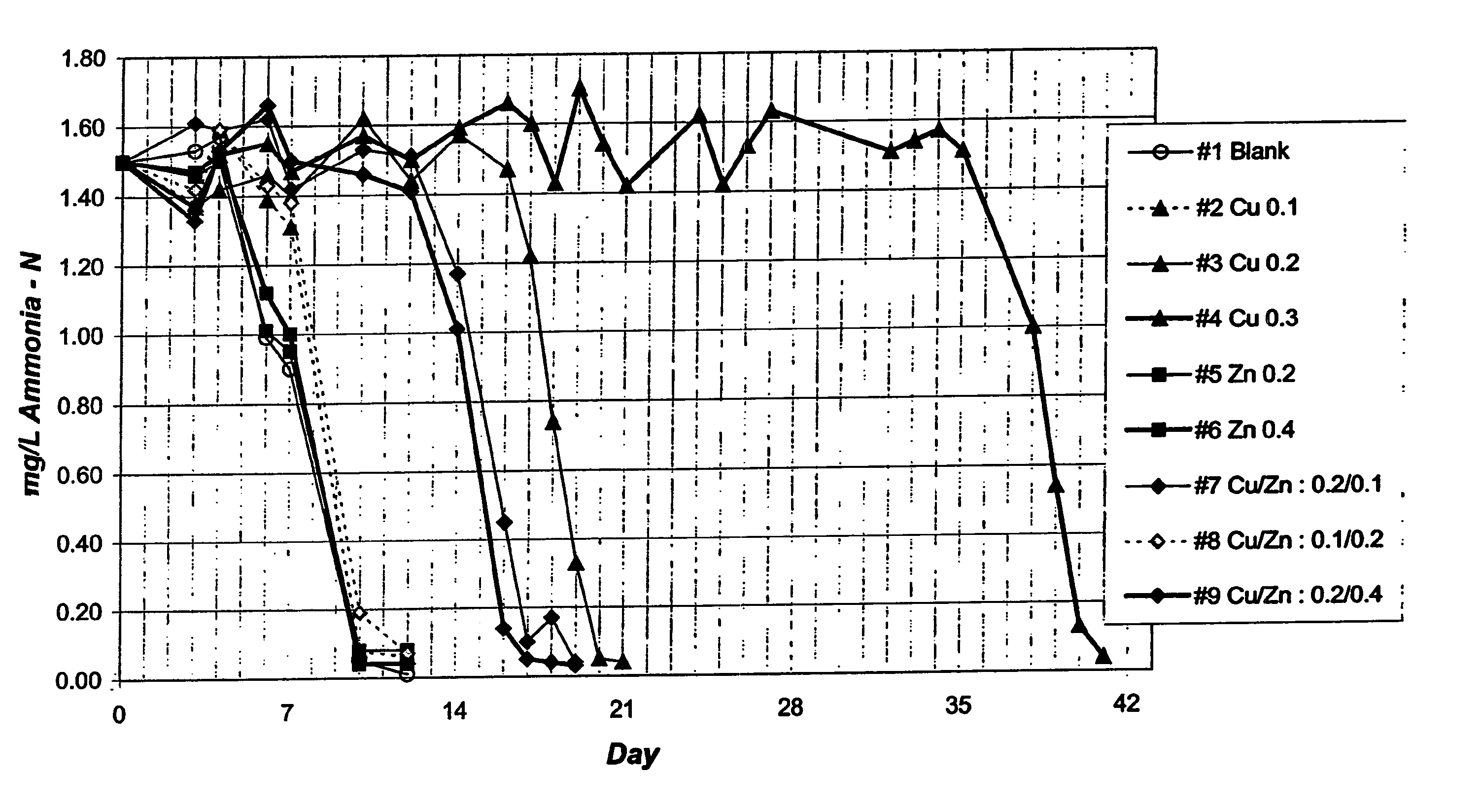
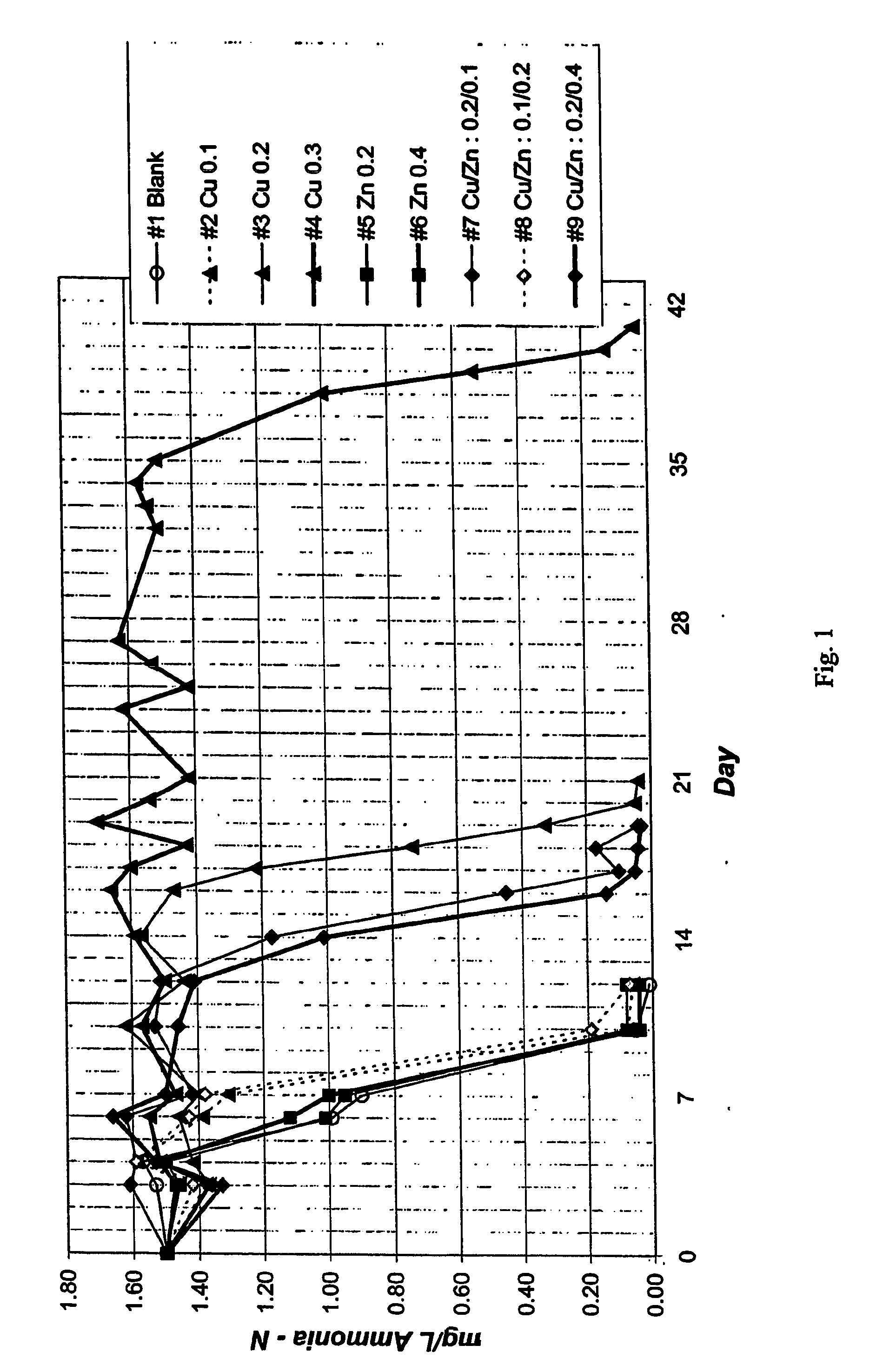
[0026] After the elimination of chlorine, a chloraminated water bulk sample was dosed with excess ammonia to achieve 1.50 mg / L ammonia-N concentration. The bulk sample was dosed with ammonia oxidising bacteria, cultured from a chloraminated system.

[0027] The bulk sample was then subsampled into 9 separate portions. These portions were dosed as follows:

[0028] 1. no dosage

[0029] 2. 0.1 mg / L copper

[0030] 3. 0.2 mg / L copper

[0031] 4. 0.3 mg / L copper

[0032] 5. 0.2 mg / L zinc

[0033] 6. 0.4 mg / L zinc

[0034] 7. 0.2 mg / L copper, 0.1 mg / L zinc

[0035] 8. 0.1 mg / L copper, 0.2 mg / L zinc

[0036] 9. 0.2 mg / L copper, 0.4 mg / L zinc.

[0037] The samples were measured over subsequent days to determine the ammonia levels. The results are shown in FIG. 1.

[0038] The results of this experimented showed the ammonia level beginning to fall after about five days, and falling to a base of level of about 0.1 mg / L after about 10 days, for each of the samples not containing copper. Where 0.1 mg / L of copper was...

example 2

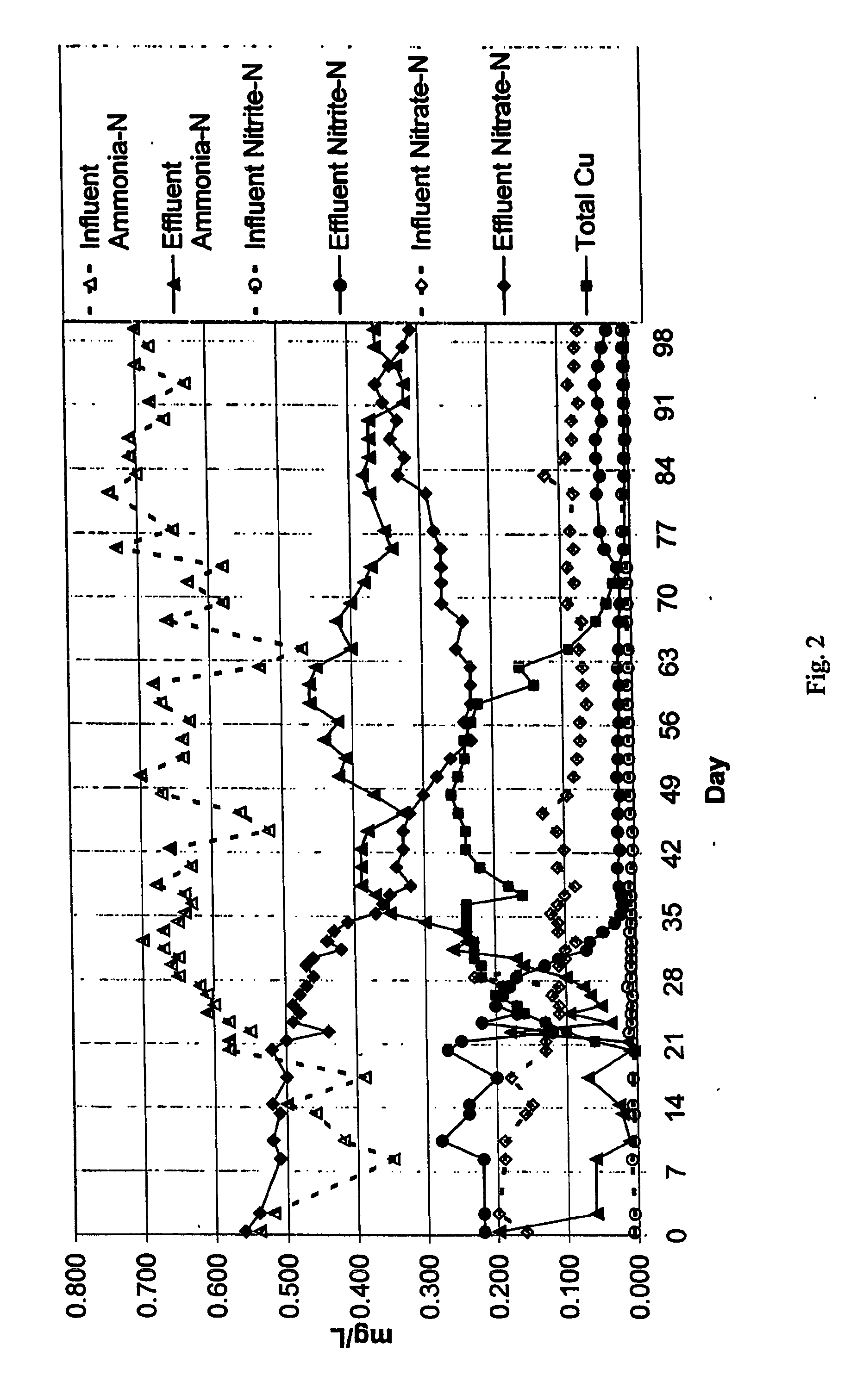
[0040] In a field trial, a reservoir having a floating cover, and a water detention period of 3.5 days, was dosed with copper sulphate to achieve a copper level of about 0.25 mg / L for a period of six weeks. The levels of ammonia, nitrite and nitrate were measured both at reservoir inlet and outlet. The results are shown in FIG. 2.

[0041] The field trial results demonstrated a substantial reduction in both nitrate and nitrite levels at the reservoir outlet, and a substantial increase in the percentage of ammonia “surviving” from inlet to outlet. These results were maintained for a period of 6 to 12 weeks following the substantial exit of copper ions from the water. This suggests a residual effect, caused perhaps by copper which has precipitated or perhaps by a lag time in the re-establishment of a biofilm.

[0042] Testing revealed a significant reduction in microbiological activity following the dosing with copper.

[0043] Further experimentation has suggested that the nitrification pr...


PUM

PropertyMeasurementUnit
concentrationaaaaaaaaaa

Abstract

A method of treating chloraminated water by adding copper ions is disclosed. The addition of copper ions inhibits microbial action in the water, thus reducing nitrification of ammonia and maintaining chloramine levels.

Description

FIELD OF THE INVENTION [0001] The present invention relates to a method of treating chloraminated water. BACKGROUND TO THE PRESENT INVENTION [0002] It is known to treat reticulated water with chlorine and ammonia in order to produce chloramines, principally monochloramine. Monochloramine is used as a disinfectant within the water. Monochloramine is produced according to the following reactions: Cl2+H2O═HOCl+HCl NH3+HOCL═NH2Cl+H2O [0003] The ration of chlorine:ammonia-nitrogen in the above reactions is approximately 5:1. The reactions may take place in the presence of excess aqueous ammonia, for instance in a concentration of about 0.2 mg / L. [0004] One problem which arises in the use of chloramines in water is that the chloramines have a propensity to decay. This decay can be a simple chemical decay, causing the equilibrium in the second equation above to move to the left. This chemical decay is very slow, and free ammonia is formed as chlorine levels are being reduced. Tests have re...

Claims


Application Information

Patent Timeline
Patent Type & Authority Applications(United States)
IPC IPC(8): C23F11/00C02F1/50C02F1/68C02F1/76
CPCC02F1/50C02F1/505C02F2303/20C02F1/76
Inventor KOSKA, LASZLO
Owner THE WATER CORP
Why Eureka
Eureka Blog
Learn More