Network load balancing apparatus, systems, and methods

a network load and load balancing technology, applied in the field of computer network systems, can solve problems such as inability to consider other aspects of traffic load allocation, and inability to consider existing load balancing methods. to achieve the effect of maximizing the total available bandwidth and avoiding out-of-order reception

Active Publication Date: 2007-03-22
TAHOE RES LTD
View PDF10 Cites 26 Cited by
  • Summary
  • Abstract
  • Description
  • Claims
  • Application Information

AI Technical Summary

Problems solved by technology

Out-of-order reception may occur because of variable and unequal delays associated with the elementary links.
These delays may be caused by differential trace lengths, by traversing buffers of different sizes, and by intermediate switching elements located between transmission points, among other possible causes.
Existing load balancing methods may not consider other aspects of traffic load allocation, however.
This may result in an underutilization of the total available bandwidth.

Method used


Image

  • Network load balancing apparatus, systems, and methods
  • Network load balancing apparatus, systems, and methods
  • Network load balancing apparatus, systems, and methods

Examples


Embodiment Construction

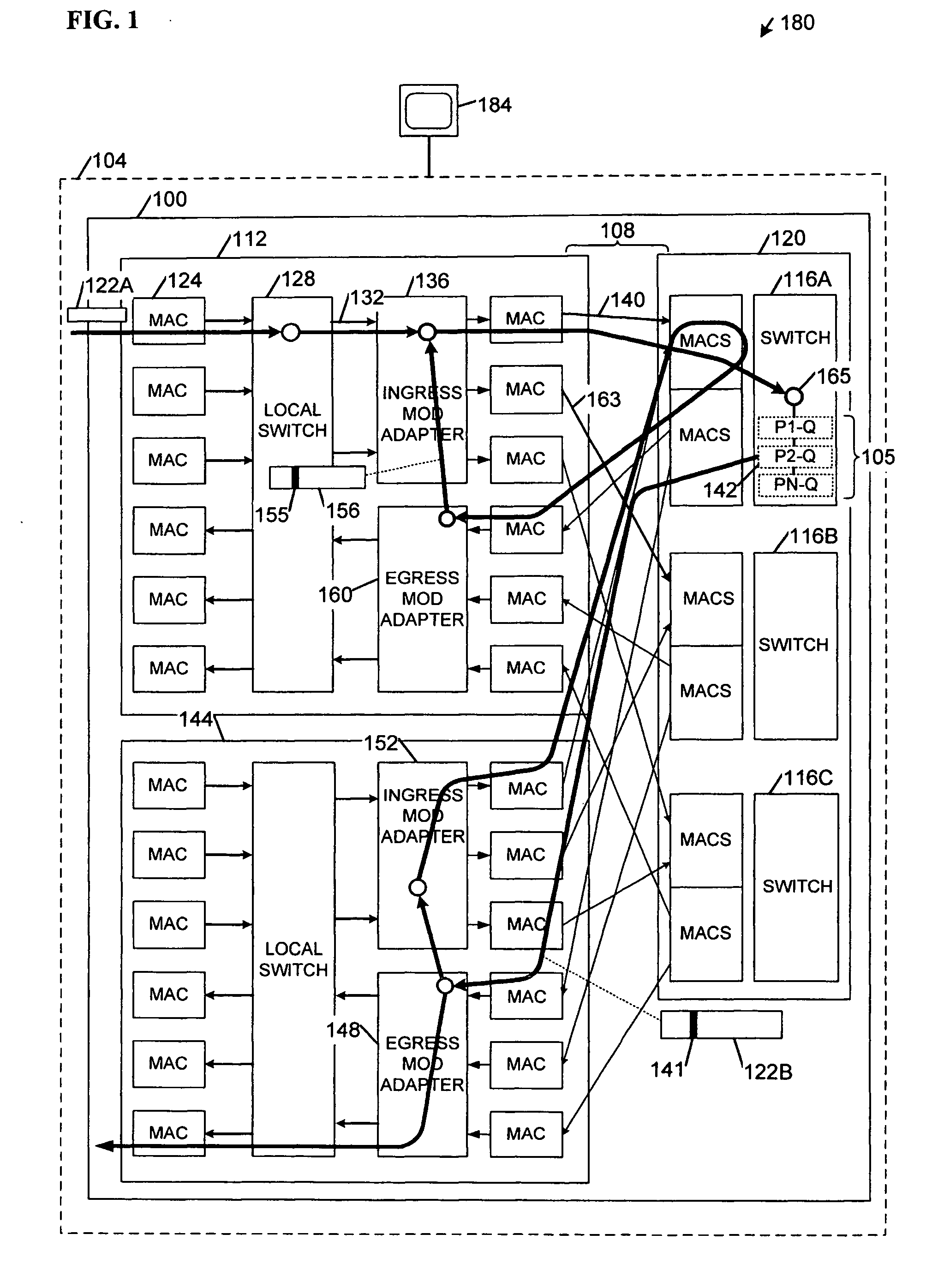
[0010]FIG. 1 comprises a block diagram of an apparatus 100 and a system 180 according to various embodiments of the invention. Some embodiments may comprise a network switch 104, including perhaps a dynamically load-balanced switch. Levels of queues 105 inside the switch 104 may be indicative of loading on connections within the switch 104. Thus, an increasing queue size may indicate that a load on a connection utilizing the queue is increasing. Queue levels may result from overall traffic patterns and from a mix of traffic of different priorities from various line cards within the switch 104. Because traffic patterns and the priority mix may change over time, a load associated with a given connection may change. Switching efficiencies may be enhanced if internal load balancing functions dynamically adapt to changes in loads on the internal connections. Ingress and egress points and / or line cards referred to hereinafter are intended to convey a direction of packet traffic flow. That...


PUM


Abstract

Apparatus, systems, methods, and articles described generally herein may receive a first packet marked with a congestion indicator (CI). Upon receipt of the CI, a load-balancing operation may be performed among a plurality of physical links upstream from a point of congestion to alleviate the congestion. Other embodiments may be described and claimed.

Description

RELATED APPLICATION [0001] This application is a Continuation-in-Part of U.S. patent application Ser. No. 11 / 219,528, titled “Network Load Balancing Apparatus, Systems, and Methods,” filed Sep. 2, 2005 (Attorney Docket No. 884.F95US1), which is incorporated herein by reference.TECHNICAL FIELD [0002] Various embodiments described herein relate to computer networking systems generally, including apparatus, systems, and methods used to perform network load balancing. BACKGROUND INFORMATION [0003] Existing Ethernet standards may define ways to aggregate multiple Ethernet communication links. The aggregated Ethernet links may behave as a single Ethernet link with a throughput greater than any one of the contributing links. That is, link aggregation may enable higher layer protocols to communicate between two points connected by several lower capacity links (“elementary links”) as if the two points were connected by a higher capacity link. According to methods specified in an Institute of...

Claims


Application Information

Patent Timeline
Patent Type & Authority Applications(United States)
IPC IPC(8): H04L12/26
CPCH04L47/10H04L47/11H04W28/08H04L47/14H04L47/31H04L47/125H04L43/0852H04W28/0284H04W8/04
Inventor HO, MICHAELWADEKAR, MANOJ
Owner TAHOE RES LTD
Why Eureka
Try Eureka