Driving device and light amount controller
a technology of driving device and light amount, which is applied in the direction of instruments, tv systems, magnetic bodies, etc., can solve the problems of increasing limiting the reduction of difficult to increase the driving speed of the above-mentioned mechanism, so as to reduce the moment of inertia of the rotor and increase the torque
- Summary
- Abstract
- Description
- Claims
- Application Information
AI Technical Summary
Benefits of technology
Problems solved by technology
Method used
Image
Examples
first embodiment
[0035] First, a description will be given of the present invention.
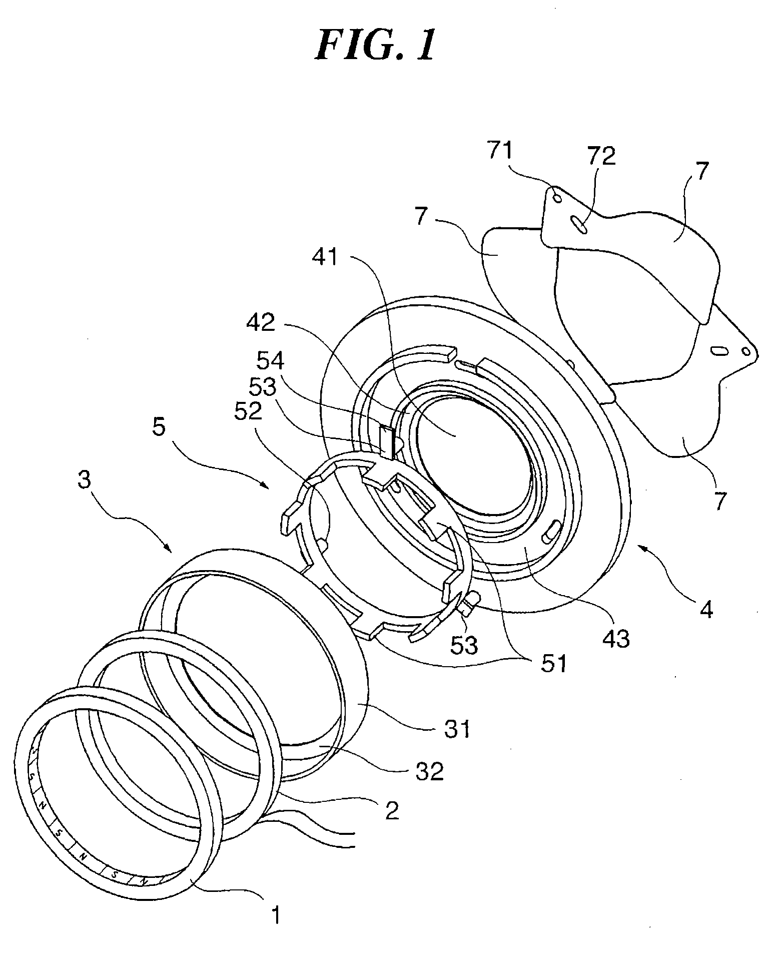
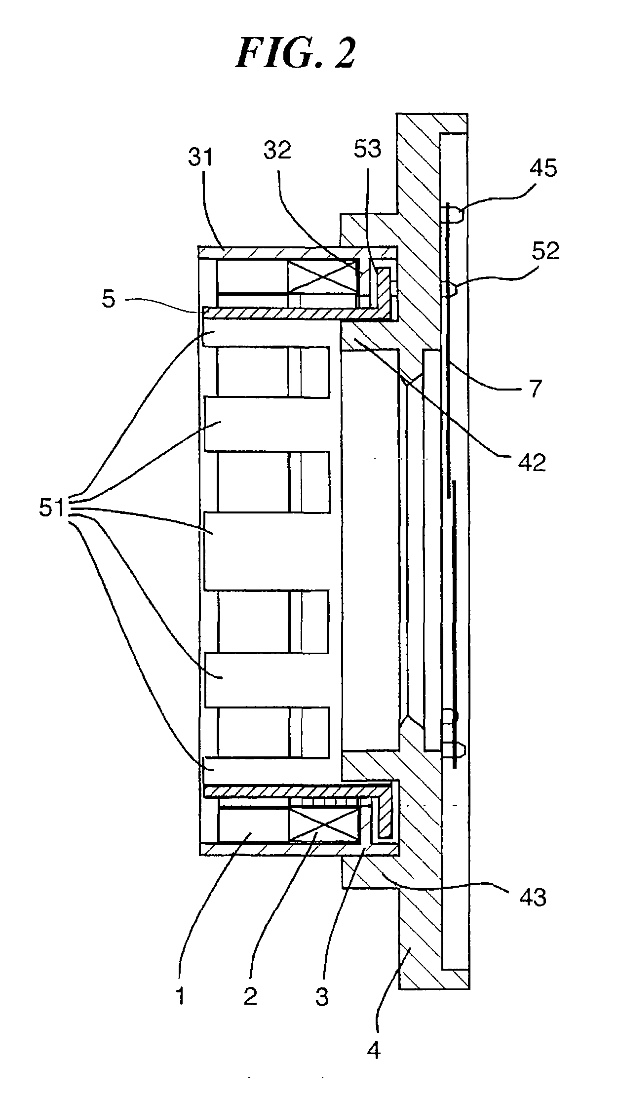
[0036]FIG. 1 is an exploded perspective view of a light amount controller according to the first embodiment. FIG. 2 is a cross-sectional view in the axial direction of the light amount controller in FIG. 1 in an assembled state thereof. FIG. 3A is a front view of the light amount controller with shutter blades thereof closed. FIG. 3B is a front view of the light amount controller with the shutter blades thereof open.
[0037] As shown in FIGS. 1 to 3, the light amount controller is comprised of a light amount adjusting mechanism including a base plate 4 and the shutter blades 7, and a driving device including a magnet 1, a coil 2, a stator yoke 3, and a rotor yoke 5.
[0038] The magnet 1 is in the form of a hollow cylinder, and has an inner peripheral surface thereof, as magnetized sections, circumferentially divided into n sections (16 sections in the present embodiment) which are magnetized such that they have alterna...
second embodiment
[0081] Next, a description will be given of the present invention.
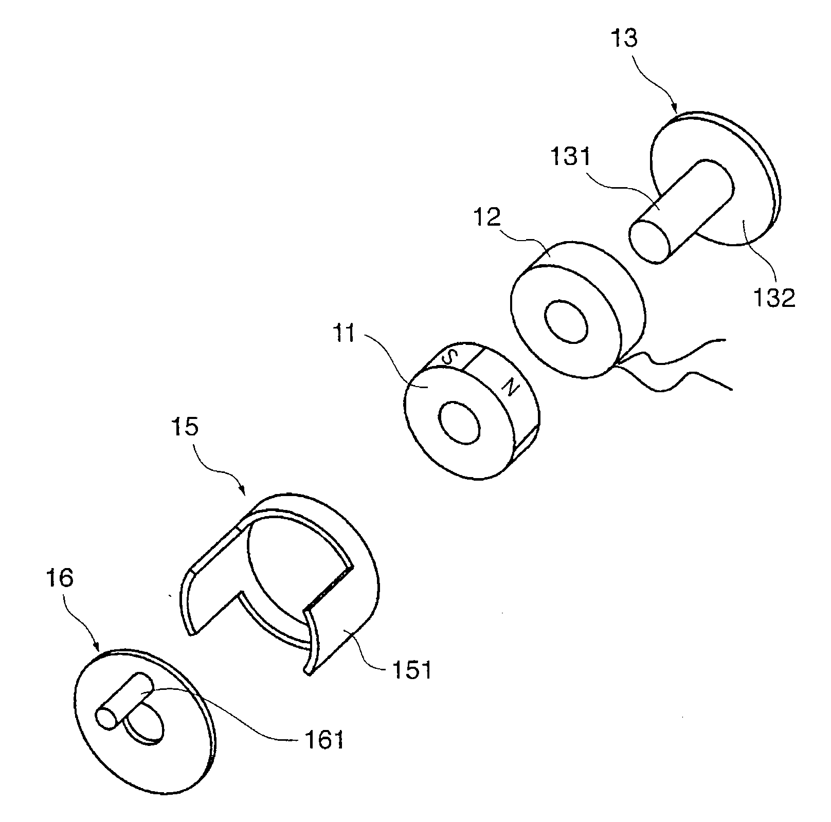
[0082]FIG. 6 is an exploded perspective view of a driving device according to the second embodiment. FIG. 7 is a cross-sectional view in the axial direction of the driving device in FIG. 6 in an assembled state thereof.
[0083] As shown in FIGS. 6 and 7, the driving device is comprised of a magnet 11, a coil 12, a stator yoke 13, a rotor yoke 15, and a rotor pin 16.
[0084] The magnet 11 is in the form of a hollow cylinder, and has an outer peripheral surface thereof circumferentially divided into n sections (four sections in the present embodiment) magnetized such that they have alternately different S and N poles (outer-periphery magnetization). The magnet 11 is disposed on an inner periphery side of the rotor yoke 15 when the driving device is assembled.
[0085] The coil 12 is formed by numerous lead wires wound into a general hollow cylindrical form, and is disposed coaxially with the magnet 11 in axially side-by-sid...
PUM
| Property | Measurement | Unit |
|---|---|---|
| angle | aaaaa | aaaaa |
| density | aaaaa | aaaaa |
| density | aaaaa | aaaaa |
Abstract
Description
Claims
Application Information
 - R&D
- Intellectual Property
- Life Sciences
- Materials
- Tech Scout
- Unparalleled Data Quality
- Higher Quality Content
- 60% Fewer Hallucinations
Browse by: Latest US Patents, China's latest patents, Technical Efficacy Thesaurus, Application Domain, Technology Topic, Popular Technical Reports.
© 2025 PatSnap. All rights reserved.Legal|Privacy policy|Modern Slavery Act Transparency Statement|Sitemap|About US| Contact US: help@patsnap.com


