Color display device using bi-directional scanning method

a color display device and scanning method technology, applied in the field of color display devices, can solve the problems of large amount of light loss, increased manufacturing cost, complicated optical system, etc., and achieve the effect of reducing the overall material cost and simplifying the optical system and circuit pattern

Inactive Publication Date: 2007-03-15
SAMSUNG ELECTRO MECHANICS CO LTD
View PDF3 Cites 6 Cited by
  • Summary
  • Abstract
  • Description
  • Claims
  • Application Information

AI Technical Summary

Benefits of technology

[0014] Accordingly, the present invention aims to provide a single panel type color display device that can simplify its optical system and circuit pattern and thus reduces the overall material cost considerably by reducing the number of panels by two compared to a three panel type color display device by employing a single panel using a single optical modulator element.
[0015] Also, the present invention aims to provide a single panel type color display device using a bi-directional scanning method, due to which the scanning frequency of a scanner reduces by half compared to one using a unidirectional scanning method, so that a manufacturing specification can be simplified and the life span of the scanner can be lengthened.

Problems solved by technology

However, in the liquid crystal projector, a large amount of light is lost since the light is projected to a screen by passing through a liquid crystal panel.
The aforementioned conventional three-panel type color display device should have three optical modulator elements corresponding to the three laser light sources, causing the optical system to be complicated and the manufacturing cost to increase.
Furthermore, in the case that the optical power of one of the laser light sources is weak, image quality deteriorates.

Method used


Image

  • Color display device using bi-directional scanning method
  • Color display device using bi-directional scanning method
  • Color display device using bi-directional scanning method

Examples


Embodiment Construction

[0042] Hereinafter, embodiments of the invention will be described in more detail with reference to the accompanying drawings. In the description with reference to the accompanying drawings, those components are rendered the same reference number that are the same or are in correspondence regardless of the figure number, and redundant explanations are omitted.

[0043] An optical modulator applicable to the present invention will first be described before discussing embodiments of the present invention.

[0044] The optical modulator can be divided mainly into a direct type, which directly controls the on / off state of light, and an indirect type, which uses reflection and diffraction. The indirect type may be further divided into an electrostatic type and a piezoelectric type. Optical modulators are applicable to the embodiments of the present invention regardless of the operation type.

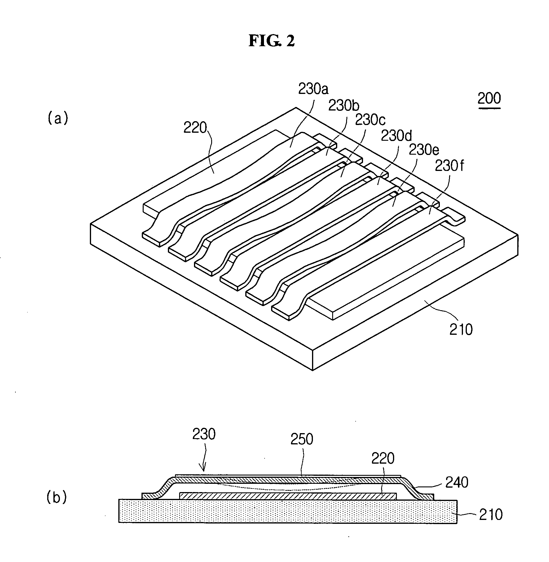
[0045] FIGS. 2(a) and (b) show the configuration of GLV (grating light valve) device, one of the ligh...


PUM


Abstract

A bi-directional scan type color display device is disclosed, comprising: a light source part emitting color lights according to a light source control signal; an optical modulator element modulating the color lights according to an optical modulator control signal, thereby generating diffracted lights; a scanner bi-directionally scanning and then projecting the diffracted lights emitted from the optical modulator element according to a scanner control signal; and an image control circuit controlling the light source part, the optical modulator element and the scanner by transferring the light source control signal, the optical modulator control signal and the scanner control signal thereto in correspondence with image information which will be displayed on the screen.

Description

BACKGROUND [0001] 1. Technical Field [0002] The present invention relates to a color display device, in particular, to a color display device outputting a two dimensional image by scanning a one dimensional image signal from a single optical modulator element, on a screen by employing a scanner. [0003] 2. Description of the Related Art [0004] As display technologies have advanced, the demand on large screen display devices has grown. The majority of current large screen display devices (mainly projectors) are using liquid crystals as a light-switcher. Such a liquid crystal projector has been popular due to the fact that it is smaller, cheaper, and has a simpler optical system than a CRT projector. However, in the liquid crystal projector, a large amount of light is lost since the light is projected to a screen by passing through a liquid crystal panel. A micro-machine such as an optical modulator element using reflection is employed to reduce such light loss, by which brighter image...

Claims


Application Information

Patent Timeline
Patent Type & Authority Applications(United States)
IPC IPC(8): H04N5/66H04N9/12
CPCH04N9/3129
Inventor YEO, IN-JAEYUN, SANG-KYEONGHAN, KYU-BUMRYU, SEUNG-WON
Owner SAMSUNG ELECTRO MECHANICS CO LTD
Why Eureka
Try Eureka