
Apparatus, system, and method for estimating particulate consumption

Active Publication Date: 2007-03-15
CUMMINS INC
View PDF22 Cites 33 Cited by
  • Summary
  • Abstract
  • Description
  • Claims
  • Application Information

AI Technical Summary

Benefits of technology

[0037]FIG. 11 is a graph illustrating a method to use easily obta

Problems solved by technology

The noxidation mechanism is often insufficient to keep the particulate filter at acceptable soot levels.
This causes local temperature spikes within the particulate filter, and can result in unnecessary wear on the particulate filter or even mechanical failure of the particulate filter.
Even in the ideal case, this feedback mechanism is still only intermittently dependable for determining soot levels.
First, whenever mass flow through the system is low, the delta-pressure based soot load estimate is known to be unreliable.
Further, while soot is being consumed on the particulate filter, the delta-pressure sensor is known to become unreliable due to holes developing in the soot layer.
Purely empirical models of soot consumption rates are problematic.
This is impossible, so some shortcuts must be taken and there will be operating points between and outside the data set which will yield poor results.
Purely theoretical models are also problematic.
The temperature within the particulate filter experiences gradients and localized variances which temperature measurements available for production engines cannot describe adequately.
The oxidation mechanism is also more sensitive to soot loading than the noxidation mechanism, making any such model sensitive to soot loading and distribution errors.
Therefore, errors from the models to the value of interest accumulate over time and become larger.
The inherent issues with the available soot load feedback mechanisms can force the system to not have a reliable feedback mechanism for many hours at a time.
Therefore, current systems can have large stretches of time where no information is available about the current soot loading.

Method used


Image

  • Apparatus, system, and method for estimating particulate consumption
  • Apparatus, system, and method for estimating particulate consumption
  • Apparatus, system, and method for estimating particulate consumption

Examples


Embodiment Construction

[0038] Many of the functional units described in this specification have been labeled as modules, in order to more particularly emphasize their implementation independence. For example, a module may be implemented as a hardware circuit comprising custom VLSI circuits or gate arrays, off-the-shelf semiconductors such as logic chips, transistors, or other discrete components. A module may also be implemented in programmable hardware devices such as field programmable gate arrays, programmable array logic, programmable logic devices or the like.

[0039] Modules may also be implemented in software for execution by various types of processors. An identified module of executable code may, for instance, comprise one or more physical or logical blocks of computer instructions which may, for instance, be organized as an object, procedure, or function. Nevertheless, the executables of an identified module need not be physically located together, but may comprise disparate instructions stored i...


PUM


Abstract

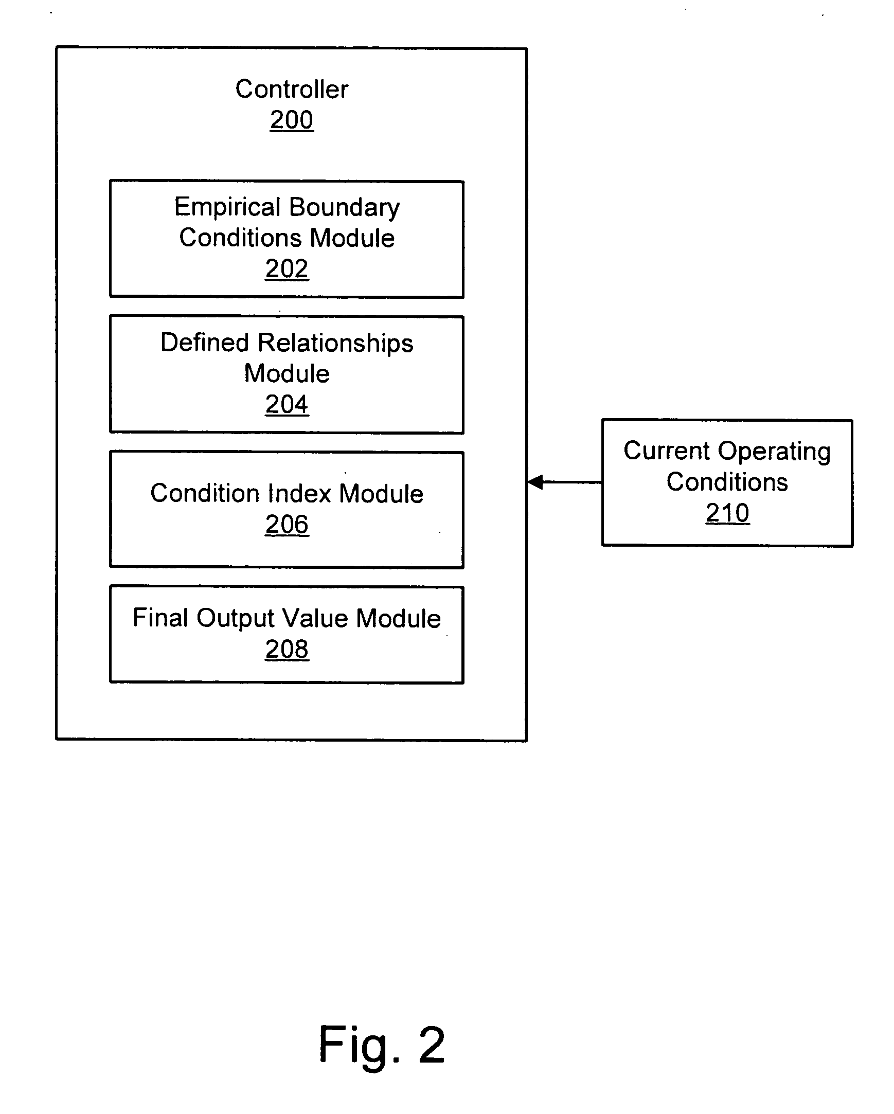
An apparatus, system, and method are disclosed for robustly estimating soot oxidation rates on a particulate filter. The invention uses empirically measured soot consumption rates as defined boundary rates, and operates between those rates using theoretical relationships between soot consumption and various operating conditions. The invention may also operate outside the defined boundaries by extrapolating the theoretical relationships beyond the defined boundary. The invention thereby overcomes the inflexibility of empirical modeling by allowing reasonable estimates at points that are not explicitly measured, and it overcomes the sensitivity of theoretical models to non-idealities that are experienced in real applications.

Description

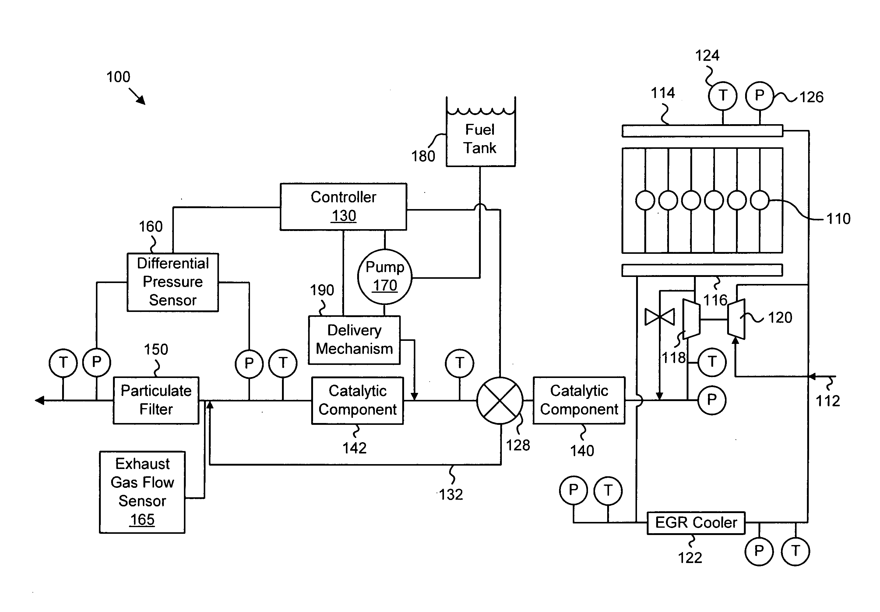
BACKGROUND OF THE INVENTION [0001] 1. Field of the Invention [0002] This invention relates to model implementation and more particularly relates to apparatuses, systems, and methods for combining theoretical and empirical knowledge as an improvement over a purely theoretical or purely empirical model. [0003] 2. Description of the Related Art [0004] Modern diesel emissions regulations are driving engine manufacturers to use particulate filters in engine aftertreatment systems. These filters accumulate soot over time, and the soot must be removed from the filter periodically. [0005] There are two primary mechanisms for removing the soot. The engine naturally generates some NO2 in the exhaust stream. At low temperatures, this NO2 oxidizes some of the soot on the filter, releasing the soot—typically as CO or CO2. This mechanism is called “noxidation.”[0006] The noxidation mechanism is often insufficient to keep the particulate filter at acceptable soot levels. Therefore, a faster oxidat...

Claims


Application Information

Patent Timeline
IPC IPC(8): F01N3/00
CPCF01N3/0231F01N9/002Y02T10/47F02B37/00F01N11/002Y02T10/40
Inventor WILLS, J. STEVE
Owner CUMMINS INC
Learn More