Surgical saw

Active Publication Date: 2007-03-08
MANI INC
View PDF15 Cites 71 Cited by
  • Summary
  • Abstract
  • Description
  • Claims
  • Application Information

AI Technical Summary

Benefits of technology

[0008] Accordingly, the present invention is conceived as a solution to the above-described problems of the conventional art, and has as its object to provide a surgical saw that can be used easily in tight places and has adequate cutting power.
[0013] A surgical saw according to a first aspect of the present invention can maintain flexibility by alternating portions where abrasive particles are affixed for cutting with portions with no abrasive particles affixed, and therefore can be used in tight places. Moreover, cutting power sufficient to cut through such hard tissue as bone can be obtained with the surgical saw of the present invention. In addition, according to a second aspect of the present invention, auxiliary cutting parts are provided in addition to the cutting part to enable bone to be cut without damaging soft tissue such as bloodvessels and nerves (including thick nerves such as the spinal cord). In addition, according to a third aspect of the present invention, the surgical saw is coated with a lubricating material and can therefore prevent leakage of toxic material from the linear body, thereby improving the suitability of the surgical saw for work with living tissue. Additionally, the lubricating coating enables the surgical saw to cut smoothly.

Problems solved by technology

However, a blade-shaped saw cannot be used in tight places, and moreover, tissue such as the spinal cord and the dura mater near the bone that is cut into or completely severed is easily damaged in such operations.
Nerves (such as the spinal cord) pass through the dura mater, and particularly since the dura mater is thin and soft it is easily damaged.
If the dura mater is damaged, the nerves can also be damaged, leading to such serious conditions as hemiplegia.
However, the saw described in Registered Utility Model No. 3018201, because it coarsens the surface of metal wire, suffers from inadequate cutting power.
In addition, the wire is strung straight between the tips of the arms, which necessitates a working space at least equal to the length of the wire and thus makes the saw difficult to use in tight places.

Method used


Image

  • Surgical saw
  • Surgical saw
  • Surgical saw

Examples


Embodiment Construction

[0019] Preferred embodiments of the present invention will now be described in detail, with reference to the accompanying drawings.

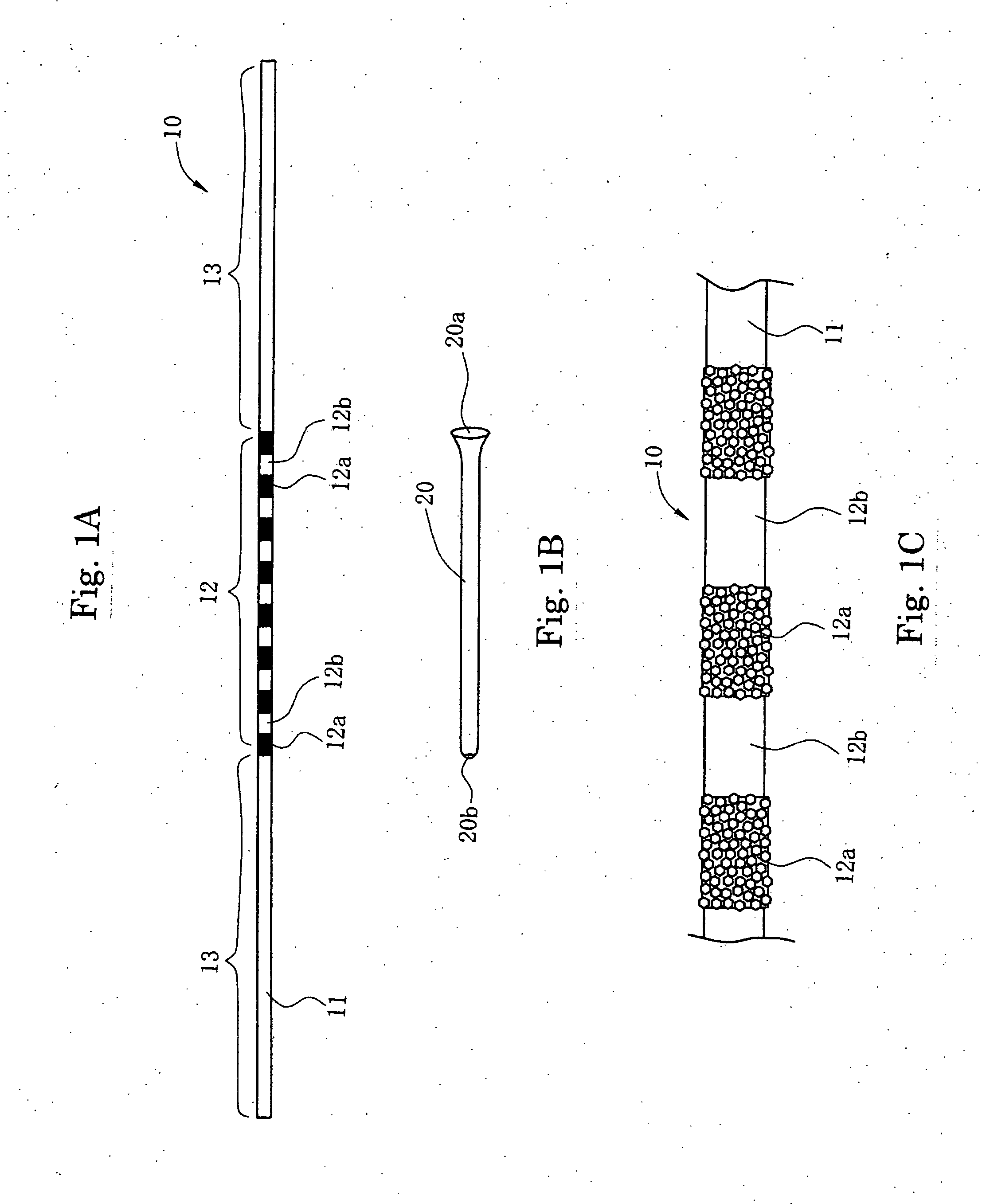
[0020]FIGS. 1A, 1B and 1C show a surgical saw according to one embodiment of the present invention, in which FIG. 1A shows an overall view, FIG. 1B shows a guide tube, and FIG. 1C shows an enlarged view of a portion of the cutting part of the surgical saw.

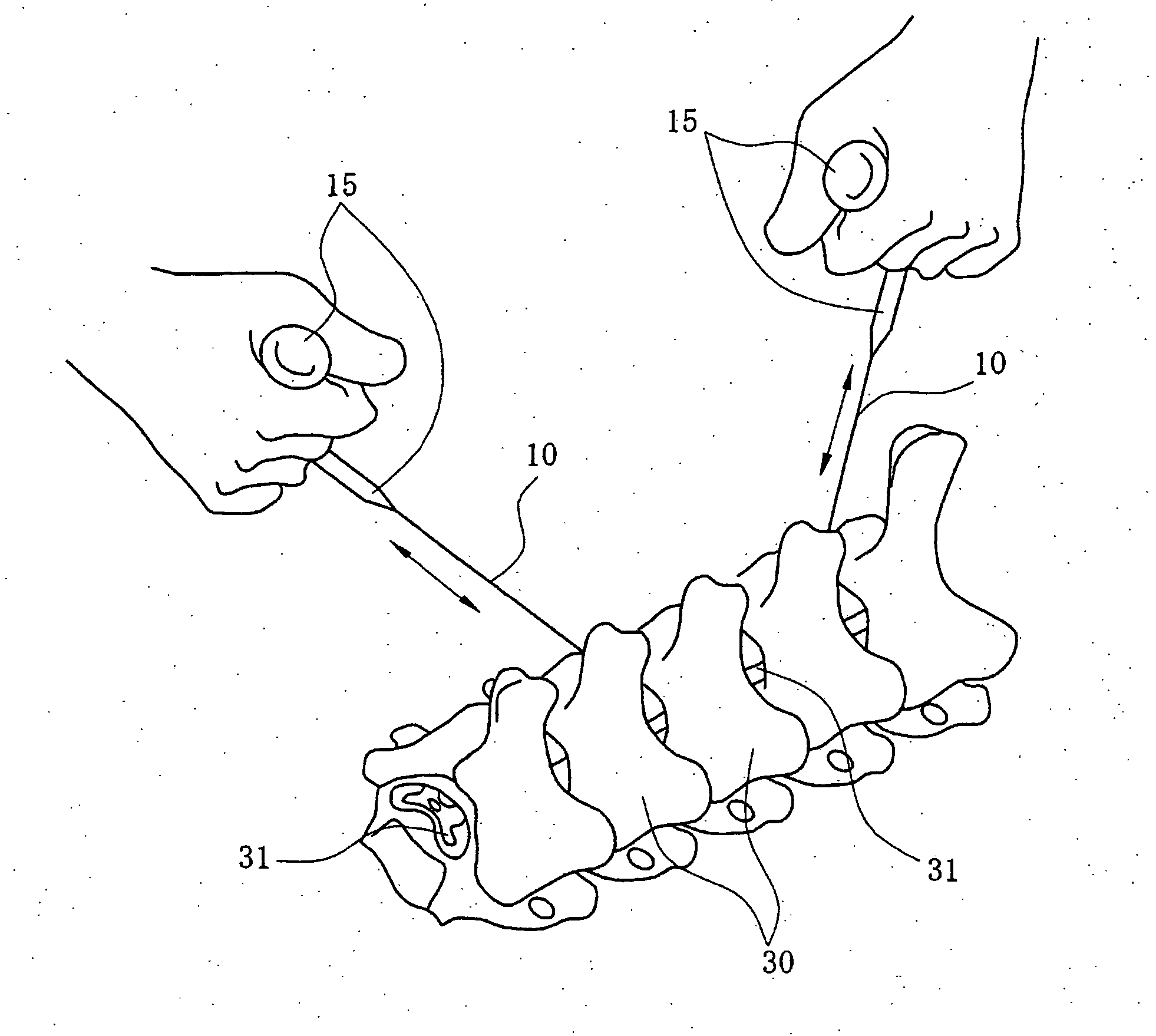
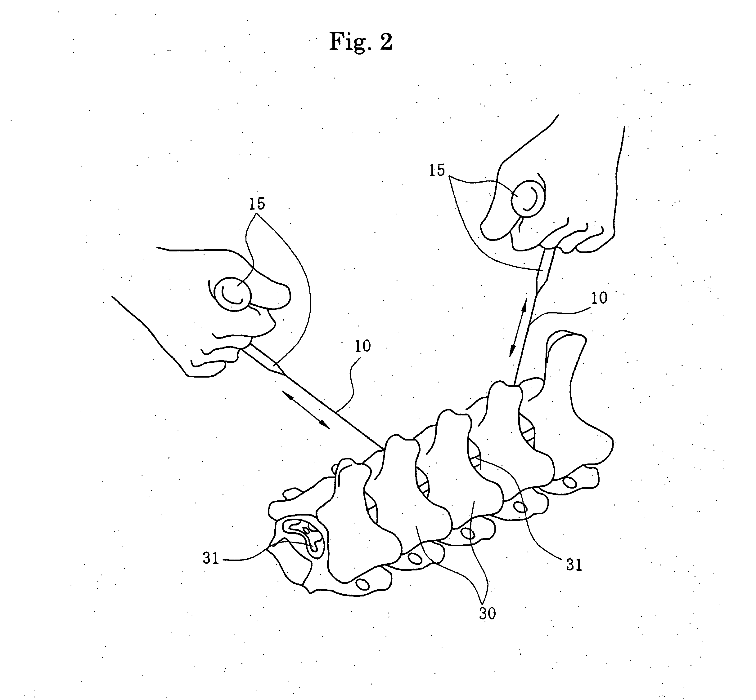
[0021] The surgical saw 10 of the present invention is composed of a linear body 11, a cutting part 12 formed on an intermediate portion of a linear body 11 and auxiliary cutting parts 13, 13 disposed on both lateral sides of each of the cutting part 12.

[0022] The linear body 11 uses a stainless steel wire having a diameter of approximately 0.3-1.0 mm. Using stainless steel prevents rust, enabling the adverse effects of rust on human tissue to be eliminated. It is preferable to use something flexible that can bend to the shape of the bone for the linear body 11 although a single strand may be used pr...


PUM


Abstract

A surgical saw for cutting bone that can be used with ease in tight places yet maintain sufficient cutting power. The surgical saw 10 has a flexible linear body made of twisted stainless steel wire and cutting parts formed on the flexible linear body. The cutting parts are made of abrasive material affixed to the flexible linear body 12a alternating with portions of the flexible linear body with no abrasive particles 12b. Auxiliary cutting parts 13 of lesser cutting power may be provided along both lateral sides of each of the cutting parts 12.

Description

BACKGROUND OF THE INVENTION [0001] 1. Field of the Invention [0002] The present invention relates to a surgical saw, and more particularly, to a surgical saw suitable for cutting bones such as the spine, the skull and so forth. [0003] 2. Background of the Invention [0004] In some surgical operations, parts of bones are removed or bones are completely cut, and at such times a special saw for bones is used. As the conventional saw used for this purpose, a thin blade-shaped saw blade is used. However, a blade-shaped saw cannot be used in tight places, and moreover, tissue such as the spinal cord and the dura mater near the bone that is cut into or completely severed is easily damaged in such operations. Nerves (such as the spinal cord) pass through the dura mater, and particularly since the dura mater is thin and soft it is easily damaged. If the dura mater is damaged, the nerves can also be damaged, leading to such serious conditions as hemiplegia. Accordingly, it is absolutely vital ...

Claims


Application Information

Patent Timeline
IPC IPC(8): A61B17/00
CPCA61B17/14A61B2017/143A61B2017/145A61B17/15A61B17/149
Inventor TOMITA, KATSUROKAWAKAMI, SHIGEOMATSUTANI, MASAAKIMATSUTANI, KANJI
Owner MANI INC
Why Eureka
Try Eureka