
Suture band

a technology of suture banding and assembly, which is applied in the field of suture banding assembly, can solve the problems of needle being driven through the sternum, difficult to place wires, and complicated tasks, and achieve the effect of reducing the discomfor

Inactive Publication Date: 2007-03-08
HANSEN DORIS HJORTH
View PDF13 Cites 30 Cited by
  • Summary
  • Abstract
  • Description
  • Claims
  • Application Information

AI Technical Summary

Benefits of technology

[0008] The present invention allows easy threading of the band through the buckle, while substantially preventing retrograde movement of the band through the buckle. Furthermore, as the band passes through the buckle, the locking mechanism maintains a substantially constant contact with said mechanism, thus allowing the band to be locked at substantially any point along its length. This avoids the necessity of an apetured band and also provides for a better fit around the bone.
[0011] A strap-like elongate flexible band is preferred rather than a substantially circular wire for the reasons pointed out above. Preferably, the strap is in the range of 0.05 mm-2.0 mm thick, more preferably 0.1 mm-1.0 mm, most preferably 0.15 mm-0.3 mm thick. Most preferably, the strap has a substantially constant thickness throughout its length. Most preferably, there are no apertures present capable of engaging any part of the locking mechanism. The width of the strap is preferably in the range of 2.0 mm-1.0 cm wide, more preferably 3.0 mm-6.0 mm wide, most preferably 4.0 mm-5.0 mm wide. The length of the strap should be sufficient to encircle the bone being encircled or clamped and be capable of being threaded through the locking mechanism. The strap may have a substantially constant width and / or thickness. Alternatively, the width or thickness of the strap may be tapered towards the needle-mounted end of the strap. This enables the strap to more easily pass through the tissue. In this embodiment, the width of the strap is relatively narrow proximate the needle. The width is gradually increased, preferably constantly, until a predetermined width is obtained closer to the buckle-mounted end of the strap.
[0012] To one end of the strap there is attached a needle which is appropriately shaped in order to enable efficient penetration of tissue. In a preferred embodiment, the needle is sickle shaped. This enables the needle to “encircle” the bone more easily.
[0013] The buckle is mounted at a distal end of the strap to the needle. The buckle comprises a locking head which is removably or preferably permanently joined to the end of the strap. The locking head is adapted for receiving the other end of the strap. It is possible to provide a needle which is flattened such that it may pass through the locking head and the strap may be pulled tight to fit the encircled tissue. In this embodiment, the needle is preferably made from a substantially rigid material which makes the tissue piercing easier than using a flexible material. In a particularly preferred embodiment, the needle may be detached from the strap prior to the strap being threaded through the locking head of the buckle. This may be effected by simply cutting the needle from the end of the strap, or a part of the strap proximal the needle may be provided with a line of weakening which may be sheared when appropriate.
[0018] The locking head preferably has a height in the range of 2 mm-7 mm, more preferably 3 mm-5 mm. The outer surface of the locking head is preferably relatively smooth, and substantially no part of the locking mechanism is directly exposed to surrounding tissue. This minimises the discomfort felt by a patient.

Problems solved by technology

For several bone tissue types and in particular, the sternum, this task is complicated by the physiological role played by the bone.
While this is a useful surgical technique for closing the sternum, there are certain problems associated with this procedure.
The wires are difficult to place and if to be placed transternally, the needle must be driven through the sternum, a very difficult task.
The internal mammary artery is subject to being injured during the procedure.
Also, the sharp wires often cause cutting of surgical gloves and may injure the surgeon.
Twisting the wires while tightening may produce torsional stresses and may even severely weaken or fracture the wires.
The stresses imparted by respiratory motion of the chest cage can further fatigue or break the wires.
Hence, closure of the sternum with wires is a slow and tedious if not dangerous technique.
There are a number of disadvantages associated with this assembly.
The further apart the apertures are located, the less accurate a fit is obtainable.
The band tends to be too loose or too tight.
The tendency of the surgeon is to overtighten the band which can cause damage to the bone and surrounding tissue.
Placing the apertures closer together leads to weakening of the band and is undesirable.
The crimping can lead to weakening of the band and the buckle, thus leading to the possibility of broken fragments of band and buckle being left in the tissue.
The irregular surface of the buckle can lead to discomfort of the patient.

Method used


Image

  • Suture band
  • Suture band
  • Suture band

Examples


Embodiment Construction

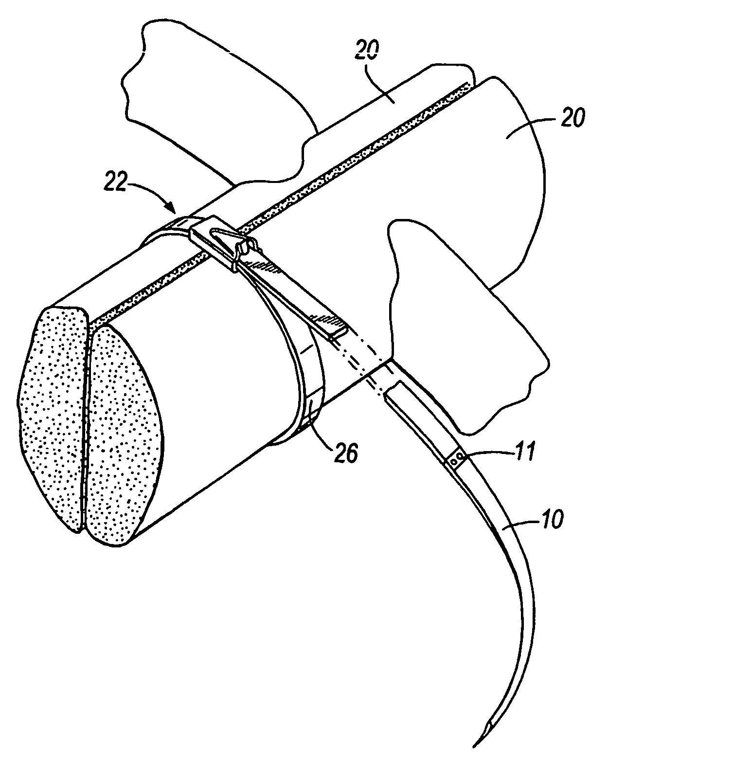
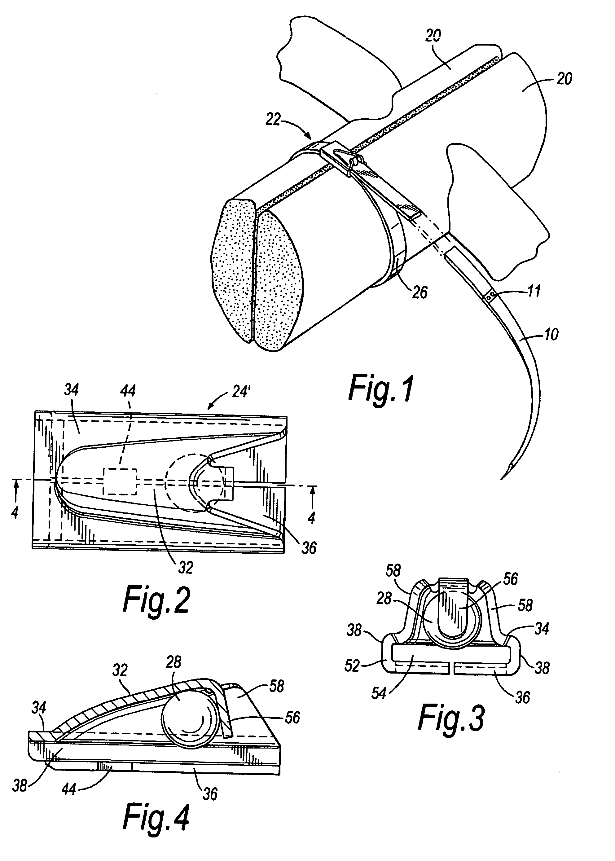
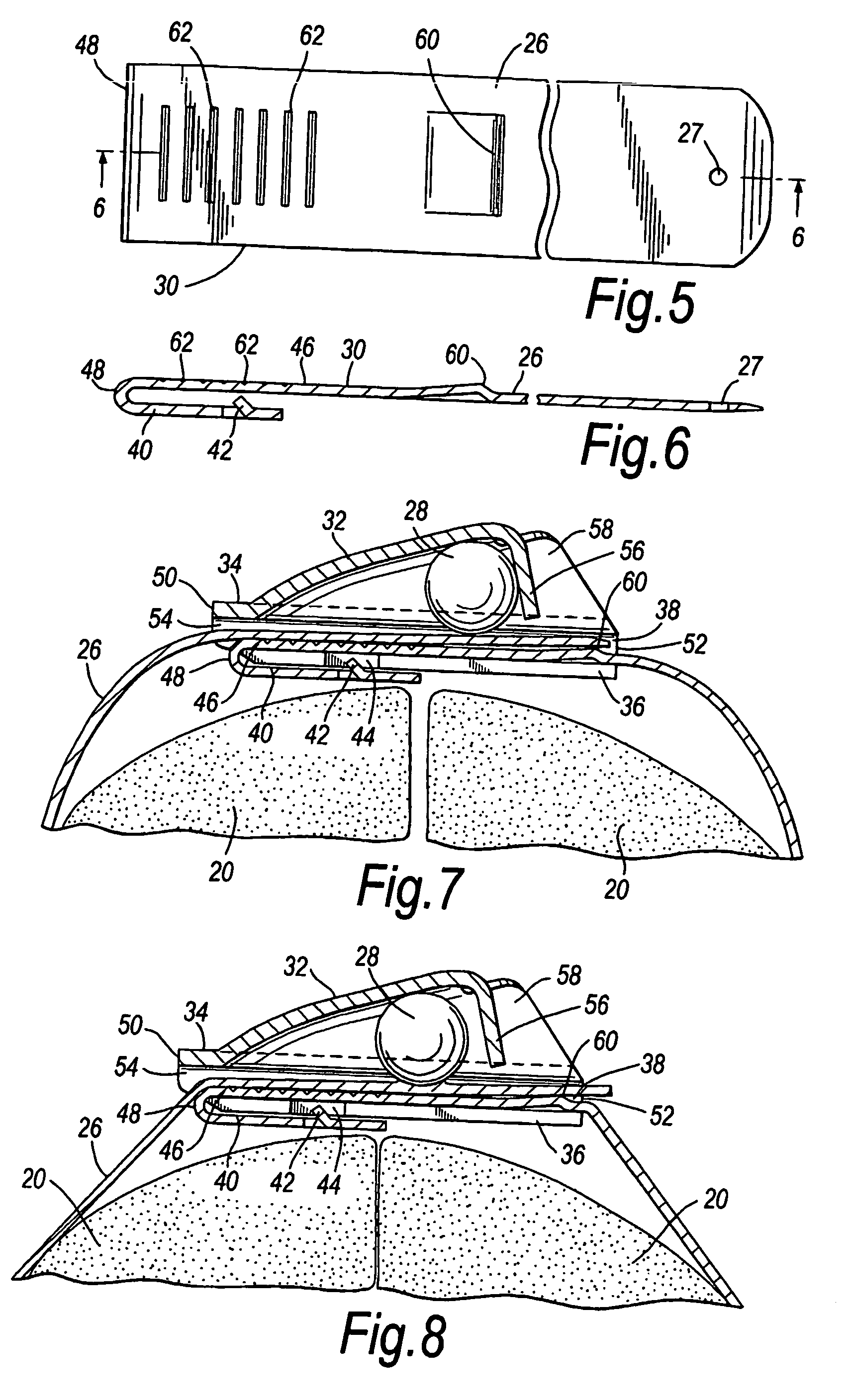
[0035] Referring now to the drawings, a first embodiment of a suture band for encircling divided bone tissue, such as the sternum 20, is generally indicated in FIG. 1 by reference character 22. The suture band is terminated at one end by a needle 10 which is attached to the end of the strap at a fixture point 11. The full length of the strap is not shown but is indicated by the hash lines in FIG. 1. Suture band 22 includes a locking head 24, an elongate strap 26 extending from the strap, and wedging means in the form of a ball or sphere 28, best shown in FIGS. 7 and 8, for retaining the strap within the locking head. Preferably the ball, head and strap are formed of stainless steel to give the suture band high strength and excellent resistance to corrosion. The ball 28 preferably has a roughened surface to ensure that it wedges securely.

[0036] The suture band of the present invention is formed by assembling a partial locking head 24′, shown in FIGS. 2-4, and the strap 26 and a hook...


PUM


Abstract

The present invention provides a suture band device comprising an elongated flexible band having first and second ends, a needle attached to the first end of the band, a buckle attached proximate the second end of the band for receiving and locking the band, characterised in the that buckle comprises a locking mechanism which enables the band to be locked at any point along its length.

Description

FIELD OF INVENTION [0001] The present invention relates to suture banding assembly for clamping and closing a wound or surgical incision, more particularly, for clamping and closing split bone tissue, for example, the sternum subsequent to thoracic surgery. BACKGROUND OF INVENTION [0002] For proper healing of split bone tissue, for example, the split sternum, the surgically opened faces must be approximated, compressed and held together rigidly. For several bone tissue types and in particular, the sternum, this task is complicated by the physiological role played by the bone. For example, the sternum is a functional component of the thoracic cage, the incessant motion of which causes continuous stresses across the sternum. Thus, any method of closing split bone, in particular, surgically split bone, must be able to maintain compression and rigidity across the closure in the face of constant stress. [0003] One technique used in sternum closure involves closing the sternum with a plur...

Claims


Application Information

Patent Timeline
Patent Type & Authority Applications(United States)
IPC IPC(8): A61B17/56A44B11/08A61B17/04A61B17/82
CPCA44B11/08A61B2017/0454A61B17/823A61B17/0487
Inventor HANSEN, DORIS HJORTH
Owner HANSEN DORIS HJORTH
Learn More