
Bone plating system for treatment of hip fractures

a bone marrow and hip fracture technology, applied in the field of orthopaedic bone marrow marrow treatment system, can solve the problems of not being available, current devices are associated with a failure risk of up to 30% for some hip fractures,

Inactive Publication Date: 2007-03-08
ZLOWODZKI MICHAL P +1
View PDF9 Cites 32 Cited by
  • Summary
  • Abstract
  • Description
  • Claims
  • Application Information

AI Technical Summary

Benefits of technology

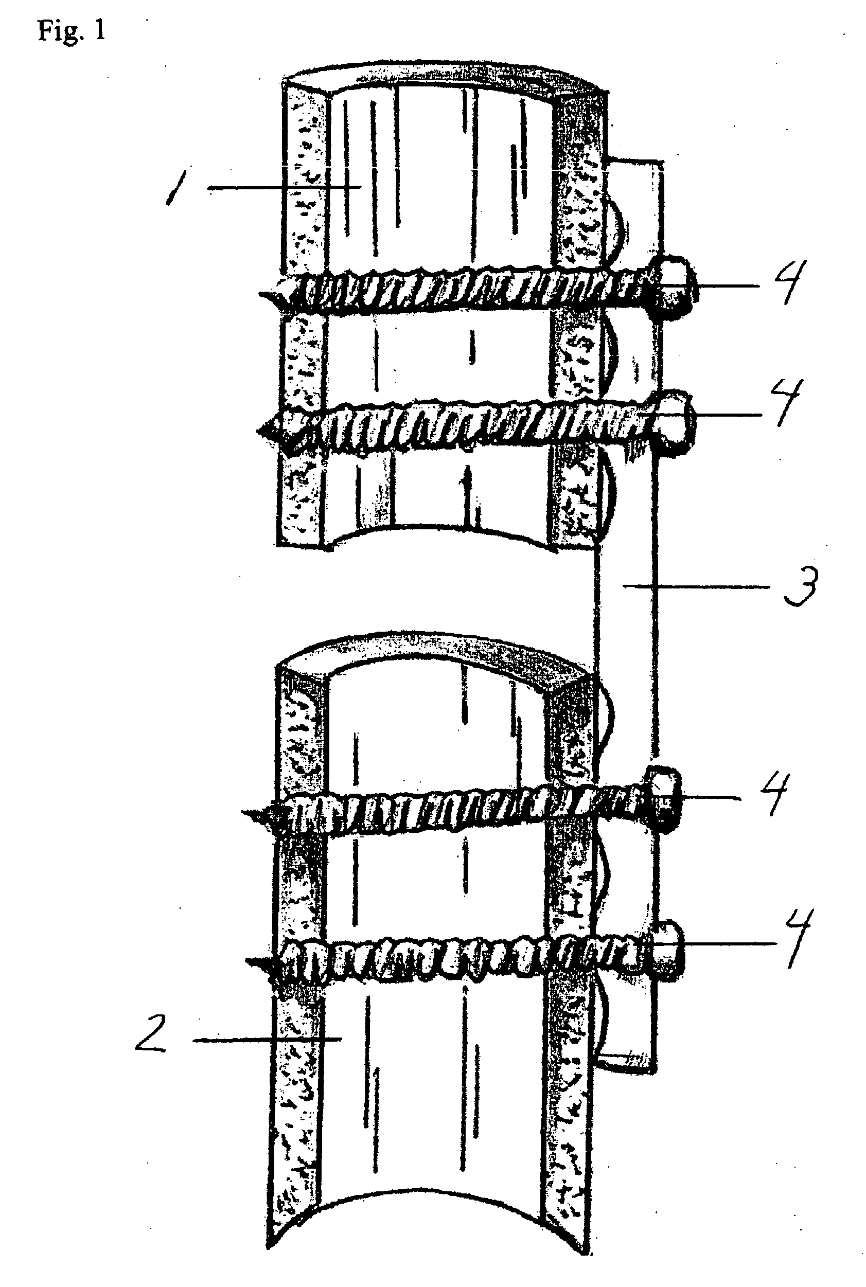
[0011] Typically bone plating systems are used to attach two bone fragments that are separated by a fracture to both ends of a plate (FIG. 1). To achieve this, there have to be at least two screws on either side (total of 4 screws) in line. Therefore the length-to-width ratio of plates is greater than 4, usually even larger. Because in the current invention the one of the two main bone fragments has no direct contact with the plate, the plate can be shorter with a length-to-width ratio greater than 2.5 (FIG. 6). The required surgical procedure can be less invasive when using a smaller plate.
[0015] One or more screw hole can be a slotted hole that allows for insertion of screws in relatively different positions to each other within the plate and therefore allows for an optimal screw configuration depending on the shape and size of the individual bone.

Problems solved by technology

Also the current devices are associated with a failure risk of up to 30% for some hip fracture types.
However, a bone plating system that allows compression of two bone fragments in the region of the proximal femur (hip) with cancellous screws and a fixed stability between screws and plate (locking screws), with or without one or more slotted holes, that allows for variable positioning of screws within a hole of the plate is not available.

Method used


Image

  • Bone plating system for treatment of hip fractures
  • Bone plating system for treatment of hip fractures
  • Bone plating system for treatment of hip fractures

Examples


Embodiment Construction

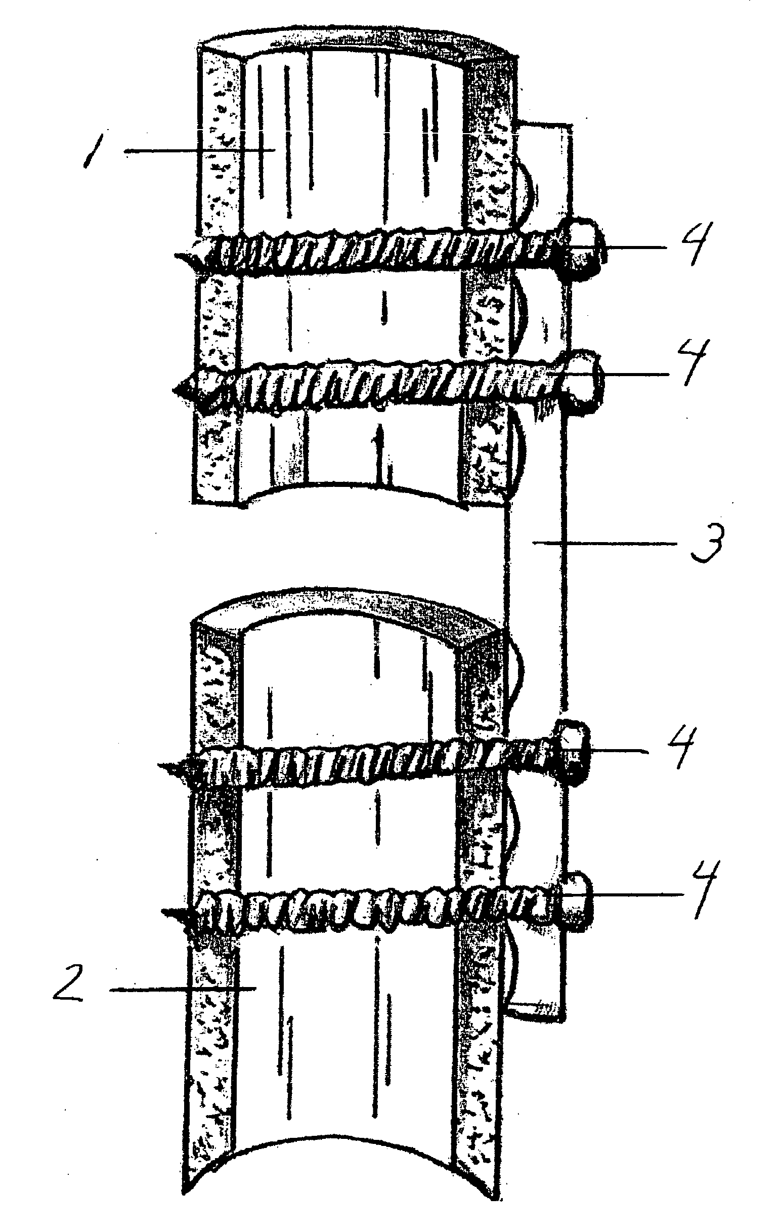
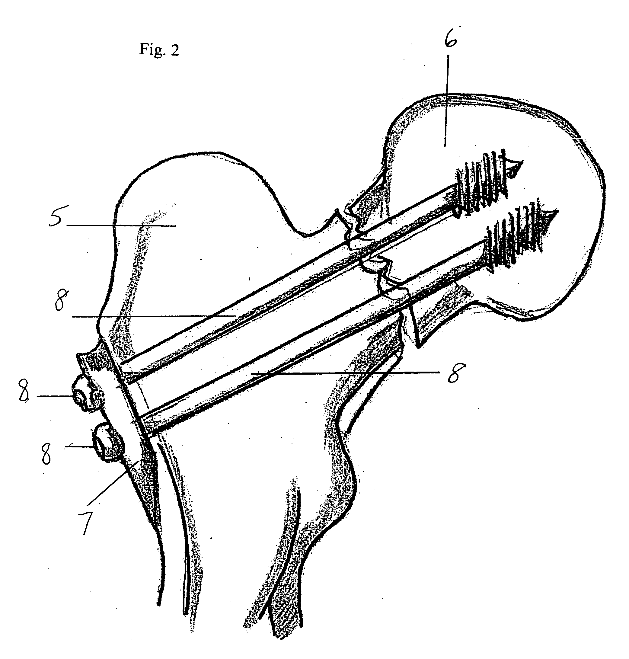
[0024]FIG. 2 depicts a situation in which one of the two bone fragments 6 is not adjacent to the plate 7, but separated by another bone fragment 5. Compression between bone fragments is being achieved by multiple screws 8. This situation is applicable to the current invention and fundamentally different from a scenario in which typically plates are used for fixation of a fractured bone depicted in FIG. 1. In the scenario depicted in FIG. 1 both bone fragments 1 and 2 are adjacent to the plate 3 and are being fixed to the plate with separate multiple screws 4. Screws can exert compression between each individual bone fragment 1 and 2 and the plate 3, but not between the bone fragments 1 and 2 themselves.

[0025] The current invention consists of a plate and multiple cancellous screws. FIG. 3 depicts a typical cancellous screw with a screw head 9 that can be threaded or nonthreaded, a non-threaded screw shaft 10, and a threaded screw tip 11. A cancellous screw can be distinguished from...


PUM


Abstract

The current invention is a bone plating system comprising a plate and screws. The plate resembles the average shape of the outer surface of the proximal femur (hip region). Cancellous screws through the plate are used to create compression between bone fragments and “locking” screws to create a stable connection between screw and plate. Each screw can accomplish either compression, stable connection with the plate or both. Screw holes in the plate can be slotted, thereby allowing for insertion of screws in relatively different positions to each other with regards to the screw entry points within the plate.

Description

BACKGROUND OF THE INVENTION [0001] The present invention is an orthopaedic bone plating system and, more particularly a bone plating system for treatment of hip fractures in which the neck of the femur is the site of the fracture. [0002] There is extensive documentation on the successful use of bone plating systems for internal fixation of fractures. Bone plating systems are generally used to attach two bone fragments that are separated by a fracture to both ends of a plate. (FIG. 1) The current invention applies to an entirely different situation in which one of the two main bone fragments can not be attached directly to the plate. (FIG. 2) This situation is typical for many hip fractures e.g. fractures of the femoral neck. [0003] There are principally two different types of screws that are being used in conjunction with bone plating systems: non-locking screws and locking screws. Both can be either cortical screws or cancellous screws. Non-locking screws achieve stability between ...

Claims


Application Information

Patent Timeline
Patent Type & Authority Applications(United States)
IPC IPC(8): A61F2/30
CPCA61B17/746A61B17/8057A61B17/8038
Inventor ZLOWODZKI, MICHAL P.BHANDARI, MOHIT
Owner ZLOWODZKI MICHAL P
Learn More