Customer illumination aperture structure

Inactive Publication Date: 2007-03-08
UNITED MICROELECTRONICS CORP
View PDF4 Cites 3 Cited by
  • Summary
  • Abstract
  • Description
  • Claims
  • Application Information

AI Technical Summary

Benefits of technology

[0007] In view of the foregoing, this invention provides a customer illumination aperture (CIA) structure for lithographic exposure, which can improve the resolution in simultaneous formation of dense, semi-dense and isolated patterns.
[0010] Since the central part is good for definition of isolated and semi-dense patterns and the off-axis part good for that of dense patterns, the overall quality of pattern transfer can be improved. By comparing the simulated aerial images and the real resist profiles obtained in experiments, it is confirmed that the through-pitch CD uniformity, mask error enhancement factor (MEEF), line-end shortening problem, pattern linearity and depth of focus (DOF) can be improved by using the illumination aperture of this invention with reduced OPC loading and cost.

Problems solved by technology

However, these methods suffer from high cost and low throughput on mask manufacturing since circuit designs are often too complex to be handled by optical proximity correction (OPC) software.
However, such an illumination aperture is not so good in definition of isolated and semi-dense patterns.

Method used


Image

  • Customer illumination aperture structure
  • Customer illumination aperture structure
  • Customer illumination aperture structure

Examples


Embodiment Construction

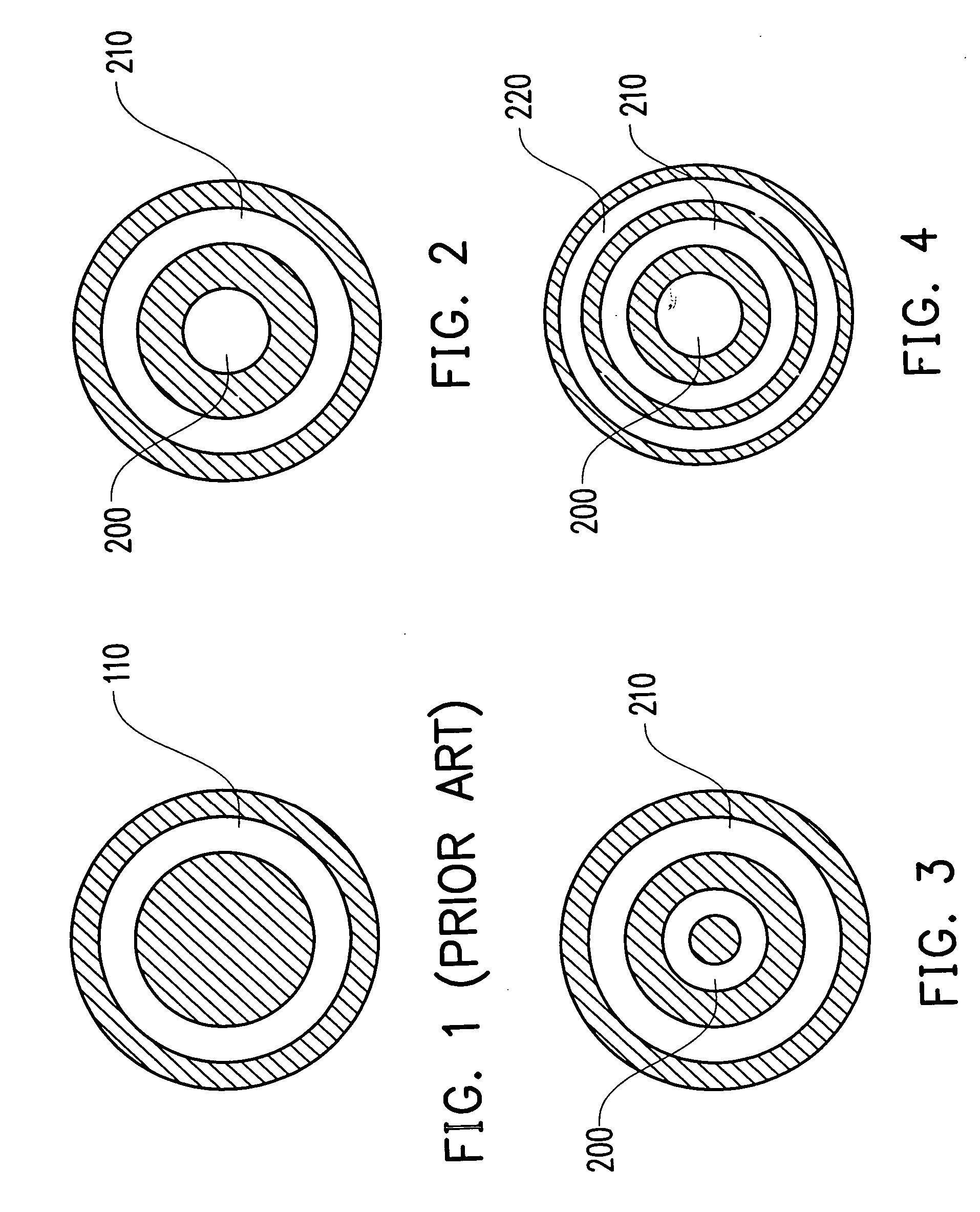
[0016]FIGS. 2-4 illustrate three examples of CIA structure of this invention, wherein each off-axis part is a single region having a ring shape.

[0017] Referring to FIG. 2, the CIA structure of this example includes a solid central part 200 and an off-axis part 210, which is a single region having a ring shape around the central part 200. Referring to FIG. 3, the central part 200 in the CIA structure may also have a ring shape.

[0018] Moreover, there may be more than one off-axis parts arranged in two or more circles around the central part 200, wherein any off-axis part can be a single region having a ring shape or includes n regions (n≧2) arranged in n-fold symmetry. As shown in FIG. 4, there are a first off-axis part 210 around the central part 200 and a second off-axis part 220 around the first one 210, wherein each of the first and second off-axis parts 210 and 220 can be a single region having a ring shape.

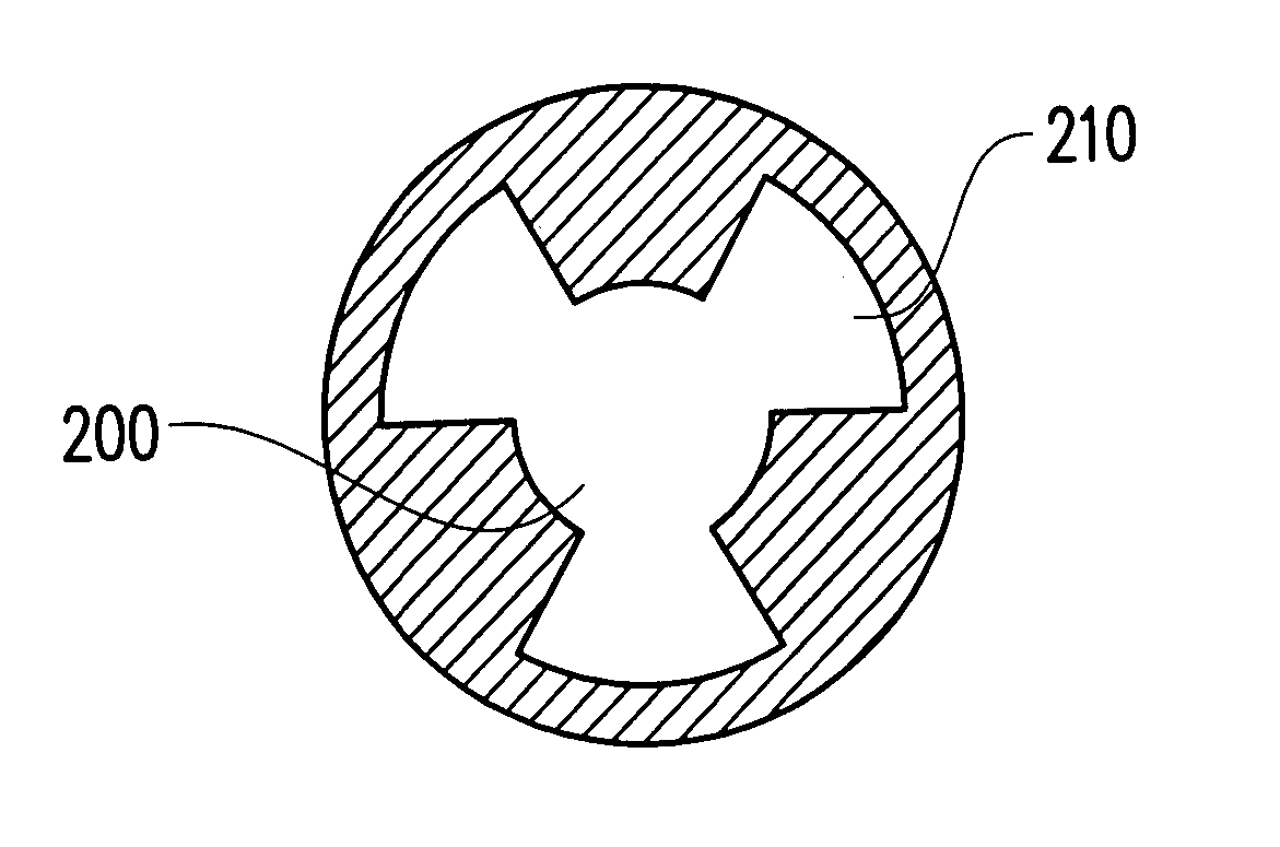
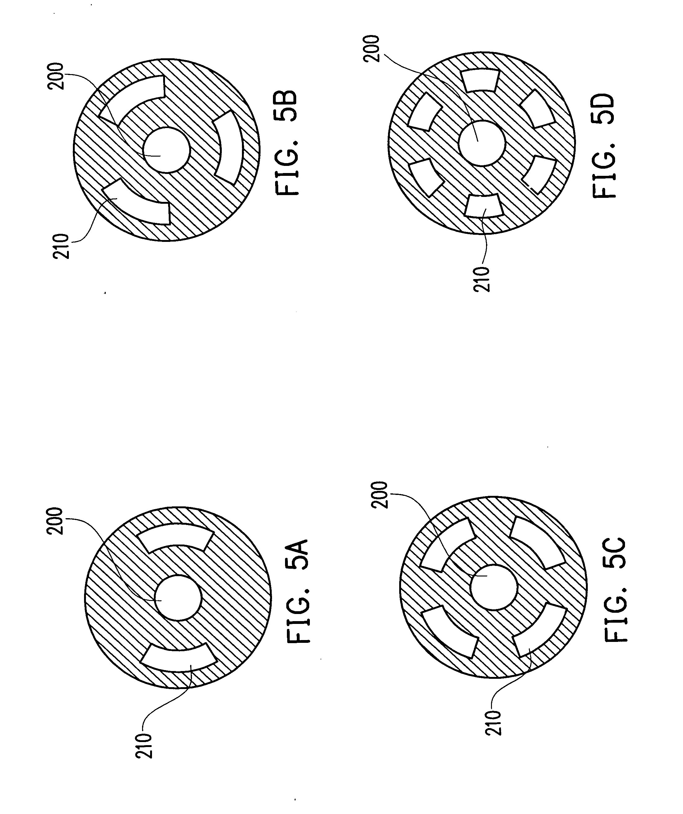
[0019]FIGS. 5A-5D illustrate four more examples of CIA structure of th...


PUM


Abstract

A customer illumination aperture (CIA) structure for lithographic exposure is disclosed, including a central part and at least one off-axis part around the central part. The off-axis part of the CIA is disposed in a symmetric manner with respect to the central part.

Description

BACKGROUND OF THE INVENTION [0001] 1. Field of the Invention [0002] The present invention relates to the lithographic technology. More particularly, the present invention relates to a customer illumination aperture (CIA) structure for lithographic exposure, which can improve the resolution in simultaneous formation of dense, semi-dense and isolated patterns. [0003] 2. Description of the Related Art [0004] In advanced semiconductor processes, especially those of 90 nm generation or below, resolution-enhanced technologies (RET) are required to achieve fine pitch resolution. Many methods have been proposed to overcome the issue of lower k1 value, such as, the methods using alternating phase-shift masks (Alt-PSM), chromeless masks, vertex masks or half-tone masks in exposure, and multiple exposure methods. [0005] Other RET methods include judicious applications of mask biasing and inclusion of additional assisting features. However, these methods suffer from high cost and low throughput...

Claims


Application Information

Patent Timeline
IPC IPC(8): G02B9/00G02B9/08
CPCG02B5/005G03F7/701G03F7/70091
Inventor LIN, LING-CHIEHHUANG, I-HSIUNGWU, TE-HUNGLIN, CHIN-LUNG
Owner UNITED MICROELECTRONICS CORP
Why Eureka
Try Eureka