
Inkjet printhead and method of manufacturing the same

a technology of printhead and inkjet, which is applied in the field of inkjet printhead, can solve the problems of reducing the driving frequency of the printhead and degrading the printing quality, and achieves the effects of high quality, high speed printing, and good ink ejection characteristics

Inactive Publication Date: 2007-03-08
SAMSUNG ELECTRONICS CO LTD
View PDF0 Cites 3 Cited by
  • Summary
  • Abstract
  • Description
  • Claims
  • Application Information

AI Technical Summary

Benefits of technology

[0011] The present general inventive concept provides a thermal inkjet printhead having good ink ejection characteristics to perform high quality and high speed printing, and a method of manufacturing of the same.

Problems solved by technology

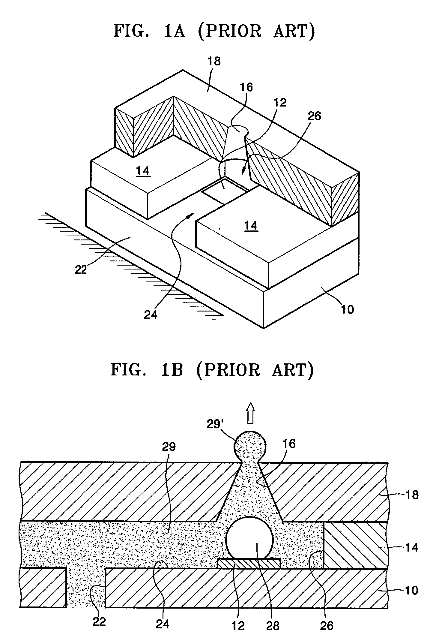
The backward ink flow may result in an insufficient pressure to eject the ink 29, and thus the ink 29 may not be properly ejected, thereby degrading printing quality.
However, the restrictor may create a problem regarding a supply of the ink 29 from the ink feedhole 22 to the ink chamber 26 after the ink 29 is ejected, which decreases a driving frequency of the printhead.

Method used


Image

  • Inkjet printhead and method of manufacturing the same
  • Inkjet printhead and method of manufacturing the same
  • Inkjet printhead and method of manufacturing the same

Examples


Embodiment Construction

[0038] Reference will now be made in detail to the embodiments of the present general inventive concept, examples of which are illustrated in the accompanying drawings, wherein like reference numerals refer to the like elements throughout. The embodiments are described below in order to explain the present general inventive concept by referring to the figures.

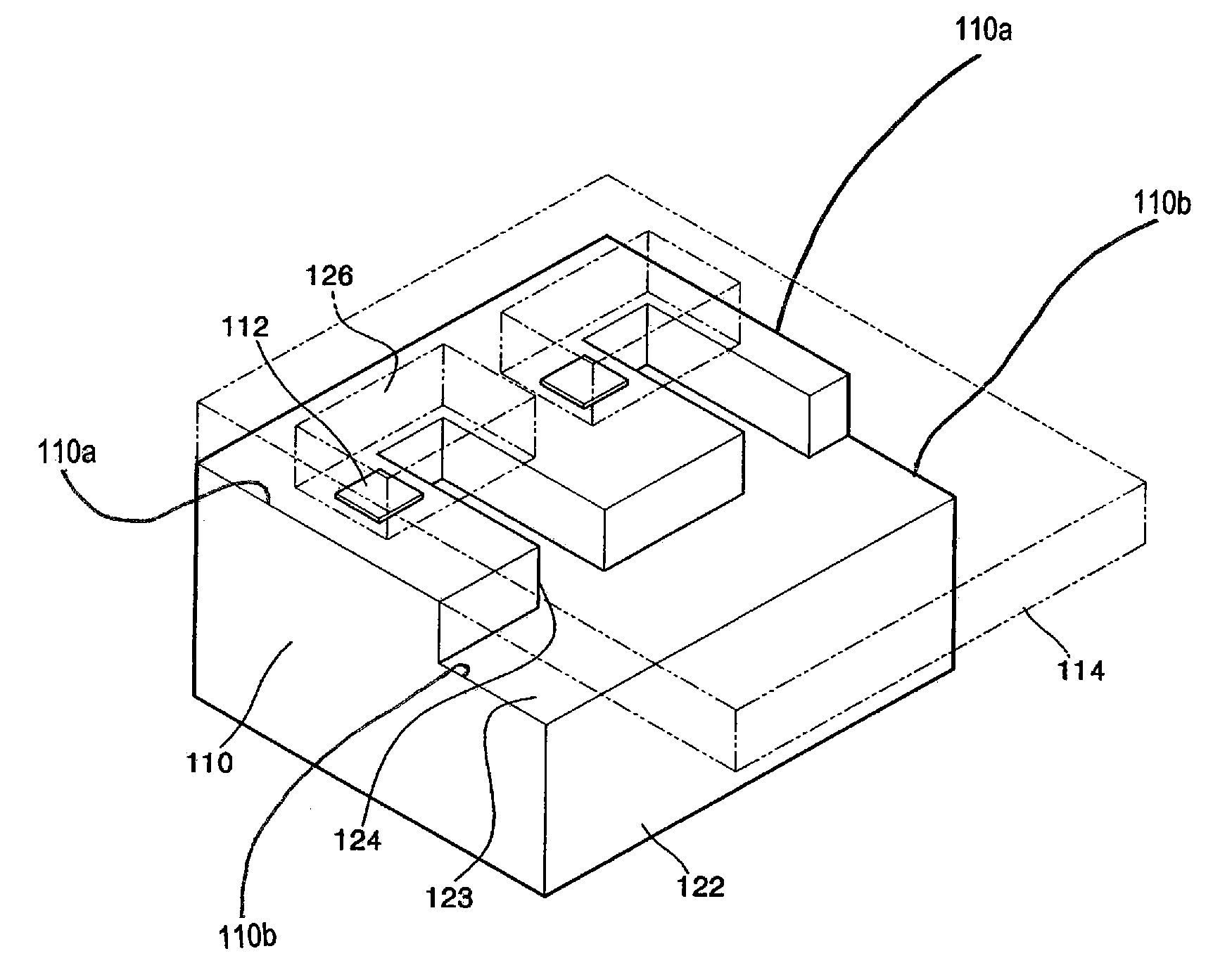
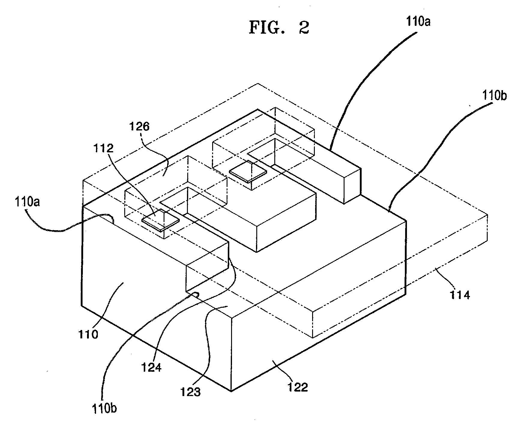
[0039]FIG. 2 is a schematic perspective view illustrating an inkjet printhead according to an embodiment of the present general inventive concept. FIG. 3 is a schematic plan view illustrating the inkjet printhead of FIG. 2. FIG. 4 is a cross-sectional view taken along line A-A′ of FIG. 3.

[0040] Referring to FIGS. 2 through 4, a plurality of heaters 112 to heat ink to generate bubbles are formed on an upper surface 110a of a substrate 110. The substrate 110 may be, for example, a silicon wafer. The heaters 112 may be heating resistors made of, for example, a tantalum-aluminum alloy, titanium nitride, and / or tungsten silicide. ...


PUM


Abstract

An inkjet printhead includes a substrate including a plurality of restrictors formed in an upper surface thereof and an ink feedhole formed in a lower surface thereof, a chamber layer stacked on the substrate and comprising a plurality of ink chambers corresponding to the plurality of restrictors including ink to be ejected, wherein each of the ink chambers is formed on an upper portion of a corresponding one of the restrictors and is connected to the corresponding one of the restrictors, a plurality of heaters formed on a bottom surface of corresponding ones of the plurality of ink chambers to heat the ink therein to generate bubbles, and a nozzle layer stacked on the chamber layer and comprising nozzles to eject the ink.

Description

CROSS-REFERENCE TO RELATED APPLICATIONS [0001] This application claims priority under 35 U.S.C. §119(a) from Korean Patent Application No. 10-2005-0082002, filed on Sep. 3, 2005, in the Korean Intellectual Property Office, the disclosure of which is incorporated herein in its entirety by reference. BACKGROUND OF THE INVENTION [0002] 1. Field of the Invention [0003] The present general inventive concept relates to a inkjet printhead and a method of manufacturing the same, and more particularly, to a thermal inkjet printhead having good ink ejection characteristics to perform high quality and high speed printing, and a method of manufacturing of the same. [0004] 2. Description of the Related Art [0005] An inkjet printhead ejects ink droplets on desired positions of recording paper in order to print predetermined color images. Inkjet printheads are classified into two types according to an ink droplet ejection mechanism thereof: a thermal inkjet printhead and a piezoelectric inkjet pri...

Claims


Application Information

Patent Timeline
Patent Type & Authority Applications(United States)
IPC IPC(8): B41J2/05
CPCB41J2/1404B41J2002/14387B41J2/14145B41J2/14016
Inventor PARK, YONG-SHIKPARK, SUNG-JOONKWON, MYONG-JONGLEE, JIN-WOOK
Owner SAMSUNG ELECTRONICS CO LTD
Learn More