
Liquid delivering apparatus and method of producing the same

a technology of liquid delivery and delivering apparatus, which is applied in the field of liquid delivery apparatus, can solve the problems of difficult to produce the desired thin piezoelectric element, and achieve the effects of small thickness, reduced rigidity of elastic plate, and good ink ejection characteristics

Active Publication Date: 2007-04-10
BROTHER KOGYO KK
View PDF11 Cites 0 Cited by
  • Summary
  • Abstract
  • Description
  • Claims
  • Application Information

AI Technical Summary

Benefits of technology

[0008]In the disclosed ink jet recording head, however, the above-described recess whose bottom serves as the thin-walled portion is formed in the clad member. The pressure generating chamber is not formed in the clad member. In the meantime, there is a demand for an ink jet recording head which exhibits good ink ejection characteristics even when the piezoelectric element is driven by a relatively low voltage. If the rigidity of the elastic plate is decreased with a decrease in the thickness thereof, the elastic plate can be oscillated by applying a relatively low drive voltage. Further, where the piezoelectric element has a small thickness, the voltage applied thereto can be lowered.
[0013]In the liquid delivering apparatus constructed according to the above-described first aspect of the present invention wherein the at least one liquid chamber is formed by etching the first layer of the laminated member, the depth of the chamber is defined by the thickness of the first layer, so that the liquid chamber has an accurate depth, permitting the apparatus to deliver the liquid with high accuracy. When the liquid in the liquid chamber is given pressure by deformation of the piezoelectric element, the amount of the liquid delivered from the liquid chamber to the exterior of the apparatus may not be accurate if the liquid chamber has an error in the configuration and the volume thereof. Where the at least one liquid chamber includes a plurality of liquid chambers, the present apparatus which permits the liquid chamber to have an accurate depth and configuration assures stable and accurate delivery of the liquid.
[0014]In the present apparatus constructed as described above, since the at least one piezoelectric element is formed on the oscillating plate reinforced by the first layer, the oscillating plate is prevented from being deformed when a stress is given to the oscillating plate upon forming of the piezoelectric element thereon. According to this arrangement, even where a laminated member is used whose second layer functioning as the oscillating plate is constituted by a thin metal layer, the piezoelectric element is laminated, with high stability, on the second layer as the oscillating plate, permitting the liquid delivering apparatus to deliver the liquid with high stability and reliability with the piezoelectric element being driven at a relatively low voltage.
[0016]In the method according to the above-described second aspect of the invention, in the liquid-chamber forming step, the second layer functions as an etching stopper and only the first layer is etched. Accordingly, the liquid chamber having an accurate depth and configuration can be formed with high accuracy. Where the at least one liquid chamber includes a plurality of liquid chambers, the present method which permits formation of the liquid chamber having an accurate depth and configuration assures stable and accurate delivery of the liquid. In the piezoelectric-layer forming step, the piezoelectric element is formed on the second layer which is in a state in which its rigidity is increased since the second layer is reinforced or backed by the first layer. Accordingly, even if a stress acts on the second layer when the piezoelectric element is formed thereon, the second layer can withstand the stress and does not suffer from deformation, so that the first layer and the second layer can be kept bonded with high stability without being separated from each other. In particular when the piezoelectric-layer forming step is carried out prior to the liquid-chamber forming step, in other words, the piezoelectric element is formed on the second layer that is reinforced by the first layer in which the liquid chambers are not yet formed, the first layer and the second layer can be kept bonded with further improved stability even after the first and second layers are subjected, in the piezoelectric-layer forming step, to very severe treating conditions such as the heat treatment conducted at a relatively high temperature where the organic substance is decomposed.
[0017]Further, in the present arrangement described above, even where a laminated member is used whose second layer functioning as the oscillating plate is constituted by a thin metal layer, the piezoelectric element is laminated, with high stability, on the second layer (as the oscillating plate) that is reinforced by the first layer, so that the liquid delivering apparatus is capable of to delivering the liquid with high stability and reliability with the piezoelectric element being driven at a relatively low voltage.

Problems solved by technology

Therefore, it is difficult to produce the desired thin piezoelectric element by simply employing a conventional method in a conventional structure.

Method used


Image

  • Liquid delivering apparatus and method of producing the same
  • Liquid delivering apparatus and method of producing the same
  • Liquid delivering apparatus and method of producing the same

Examples


Embodiment Construction

[0027]Referring to the drawings, there will be described preferred embodiments of the present invention.

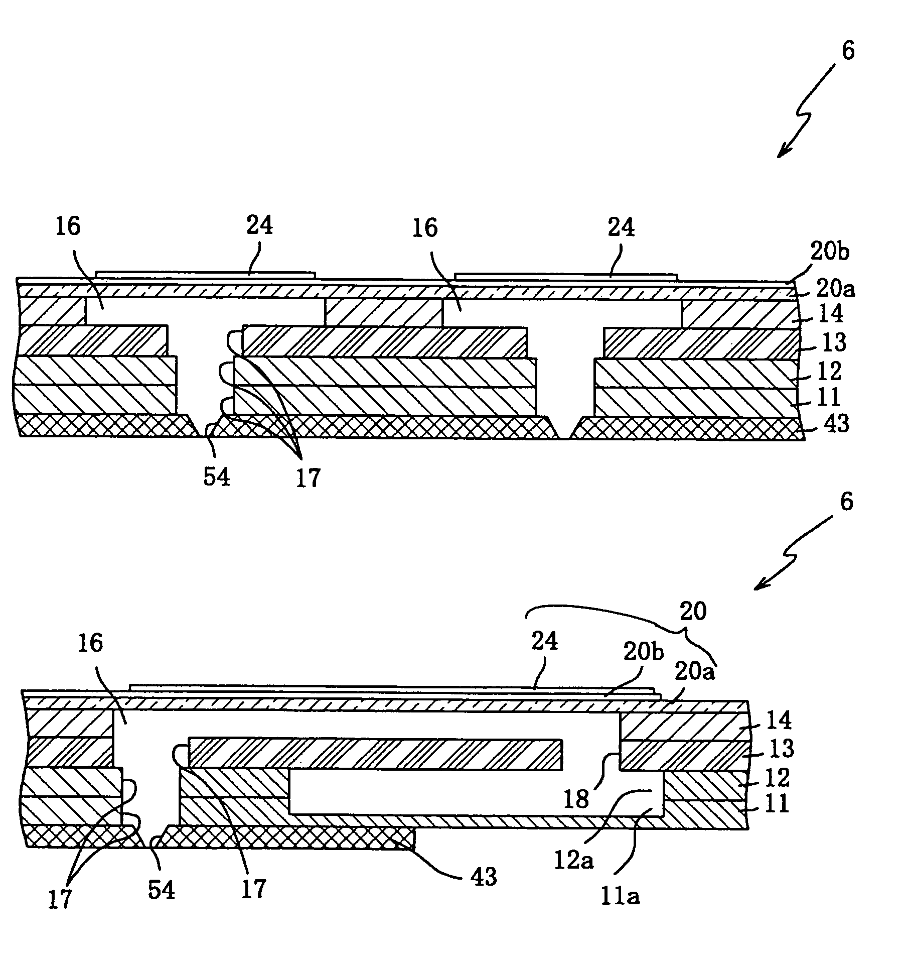
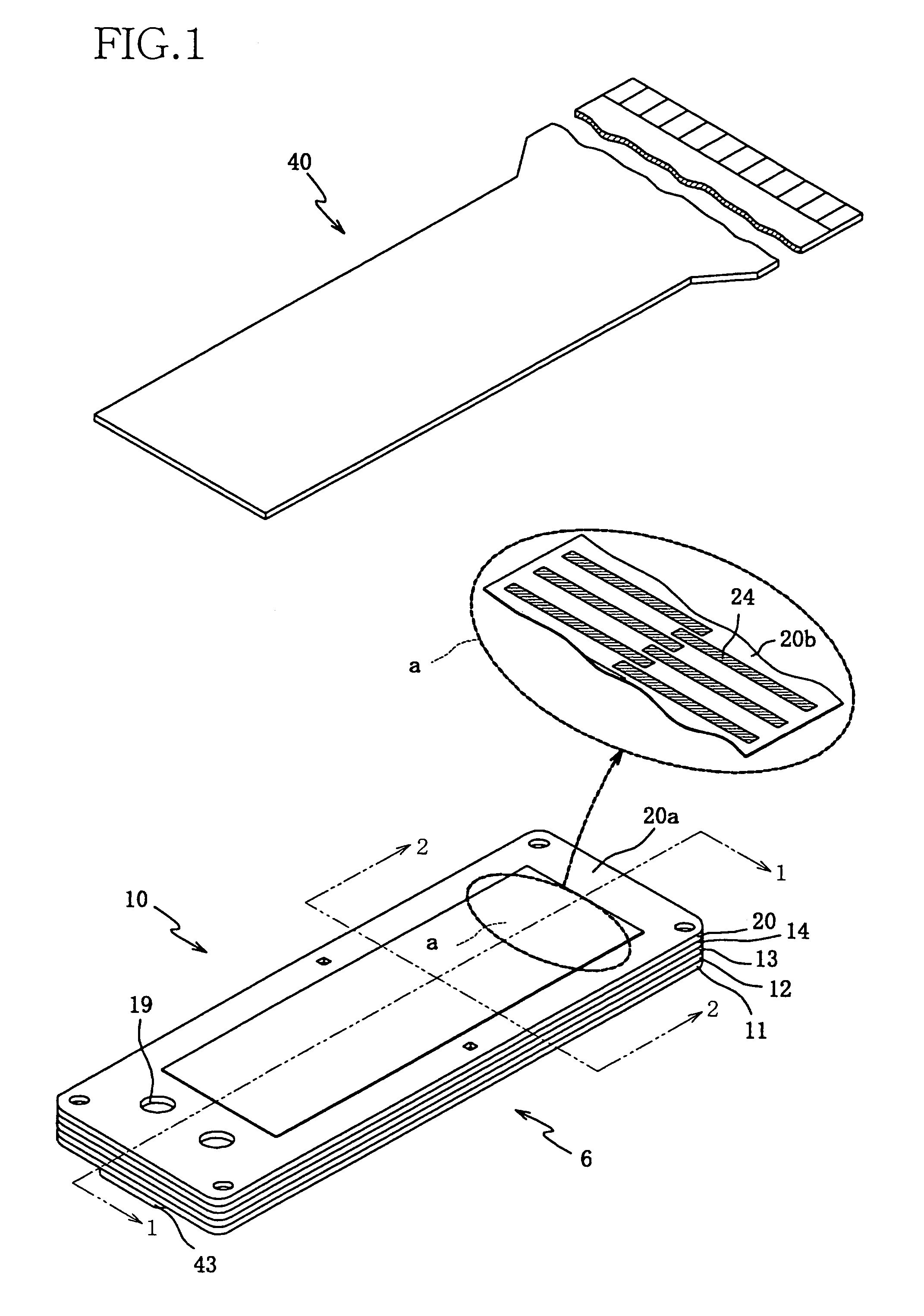
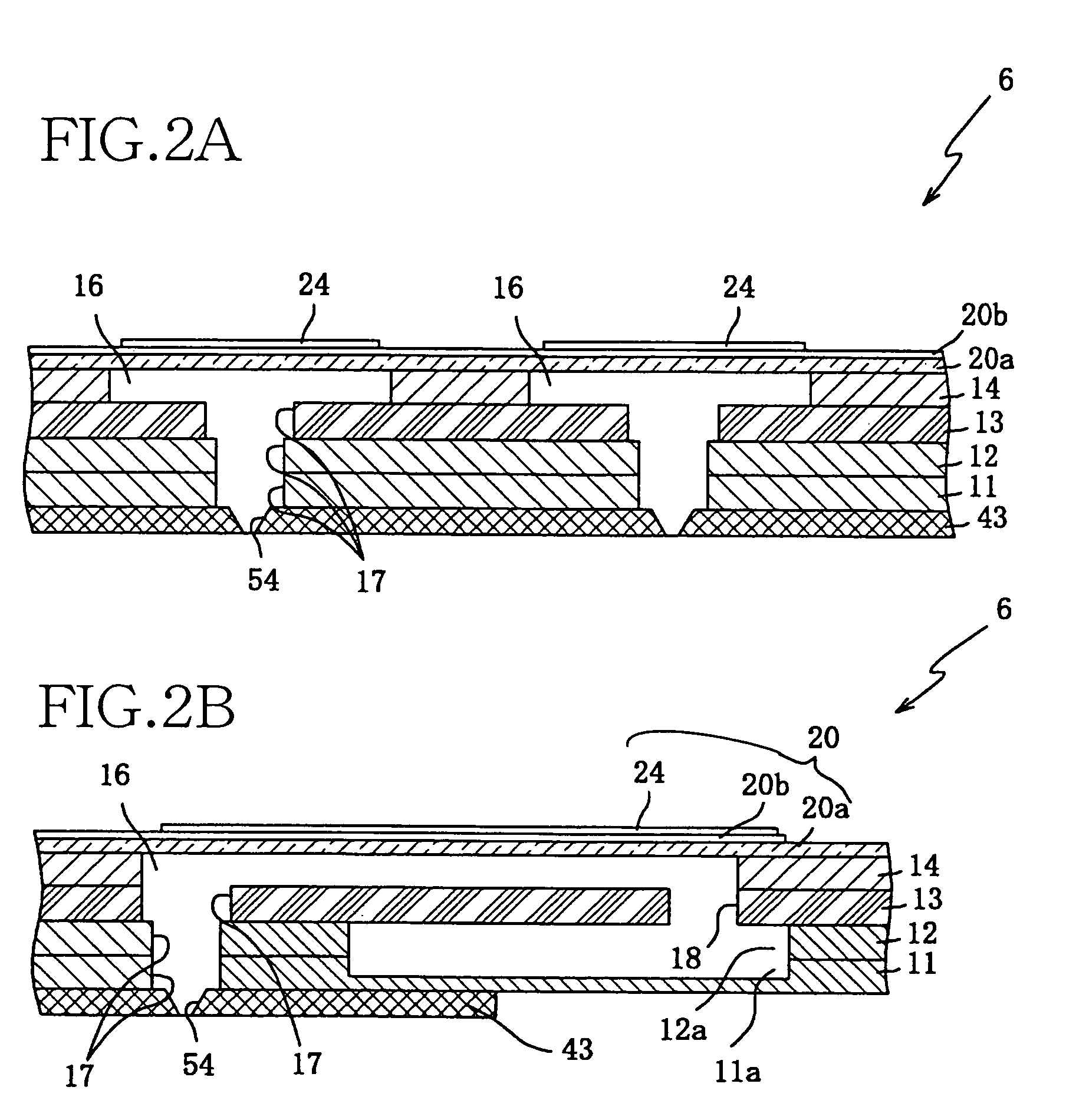
[0028]Referring first to FIG. 1 of the exploded perspective view, there is shown a liquid delivering apparatus in the form of a piezoelectric ink jet recording head 6 constructed according to a method as one embodiment of the present invention.

[0029]As shown in. FIG. 1, the piezoelectric ink jet recording head 6 has a laminated structure including a piezoelectric element 20b, an oscillating plate 20a, a cavity plate 14, a spacer plate 13, two manifold plates (second and first manifold plates) 12, 11, and a nozzle plate 43, which are arranged in this order in a direction from the top to the bottom of the head6.

[0030]The piezoelectric element 20b, the oscillating plate 20a and a plurality of individual electrodes 24 (which will be described) cooperate with each other to provide a pressure applying member 20. The cavity plate 14, spacer plate 13, two manifold plates 11, 12, and nozzl...


PUM


Abstract

A liquid delivering apparatus includes at least one piezoelectric element which deforms upon application of a drive voltage thereto, an oscillating plate on which the piezoelectric element is laminated and which is oscillated by deformation of the piezoelectric element, and at least one liquid chamber which stores liquid and which is formed adjacent to the oscillating plate on one of opposite sides thereof that is remote from the piezoelectric element. The liquid in the liquid chamber is given pressure by the deformation of the piezoelectric element, so that the liquid is delivered to an exterior of the apparatus. The liquid chamber is formed in a laminated member including a first layer and a second layer bonded integrally to each other. At least one portion of the first layer is recessed. At least one portion of the second layer is exposed.

Description

[0001]The present application is based on Japanese Patent Application No. 2003-197350 filed Jul. 15, 2003, the contents of which are incorporated herein by reference.BACKGROUND OF THE INVENTION[0002]1. Field of the Invention[0003]The present invention relates in general to a liquid delivering apparatus and in particular to such a liquid delivering apparatus including a laminated member in which at least one liquid chamber is formed and which includes an oscillating plate, wherein the liquid in the liquid chamber is given sufficient pressure by at least one piezoelectric element even where the piezoelectric element is driven by a relatively low drive voltage, so that the apparatus is capable of delivering or transporting the liquid from the liquid chamber to an exterior of the apparatus. The present invention also relates to a method of producing the liquid delivering apparatus.[0004]2. Discussion of Related Art[0005]As one example of an apparatus which delivers a liquid by actuation...

Claims


Application Information

Patent Timeline
Patent Type & Authority Patents(United States)
IPC IPC(8): B41J2/045B41J2/055B41J2/14B41J2/16
CPCB41J2/14233B41J2/161B41J2/1623B41J2/1629B41J2/1632B41J2/1645
Inventor KOBAYASHI, KAZUOSUGAHARA, HIROTO
Owner BROTHER KOGYO KK
Learn More