
Method, device, and program for producing elemental image array for three-dimensional image display

a three-dimensional image and elemental array technology, applied in static indicating devices, instruments, polarising elements, etc., can solve the problems of invariability of height, inability to achieve animation in which the depth position is continuously changed, and inability to obtain parallax information in the vertical direction

Inactive Publication Date: 2007-03-08
KK TOSHIBA
View PDF3 Cites 19 Cited by
  • Summary
  • Abstract
  • Description
  • Claims
  • Application Information

AI Technical Summary

Benefits of technology

[0010] The present invention is proposed in consideration of the aforementioned circumstances, and it is an object of the present invention to provide a method, device, and producing program of an elemental image array for three-dimensional image display in a three-dimensional image display device of a horizontal parallax type. With the method, the device, or the program, such an elemental image array is produced that a two-dimensional image can be displayed in a desired position, a desired aspect ratio of the displayed image can be maintained, and an optimum interpolating effect is achieved.

Problems solved by technology

However, if the depth position is only discretely set, an animation in which the depth position is continuously changed cannot be achieved.
In addition to that problem, in the above case where an elemental image array is to be produced through horizontal shifts of a two-dimensional image, parallax information is not obtained at all in the vertical direction.
However, the height is invariable with regular horizontal movements.
As a result, the aspect ratio of the two-dimensional image is unbalanced, and the resultant image becomes unnatural, with the two-dimensional images displayed on the near side being enlarged in the horizontal direction and the two-dimensional images displayed on the far side being enlarged in the vertical direction.

Method used


Image

  • Method, device, and program for producing elemental image array for three-dimensional image display
  • Method, device, and program for producing elemental image array for three-dimensional image display
  • Method, device, and program for producing elemental image array for three-dimensional image display

Examples


first embodiment

(First Embodiment)

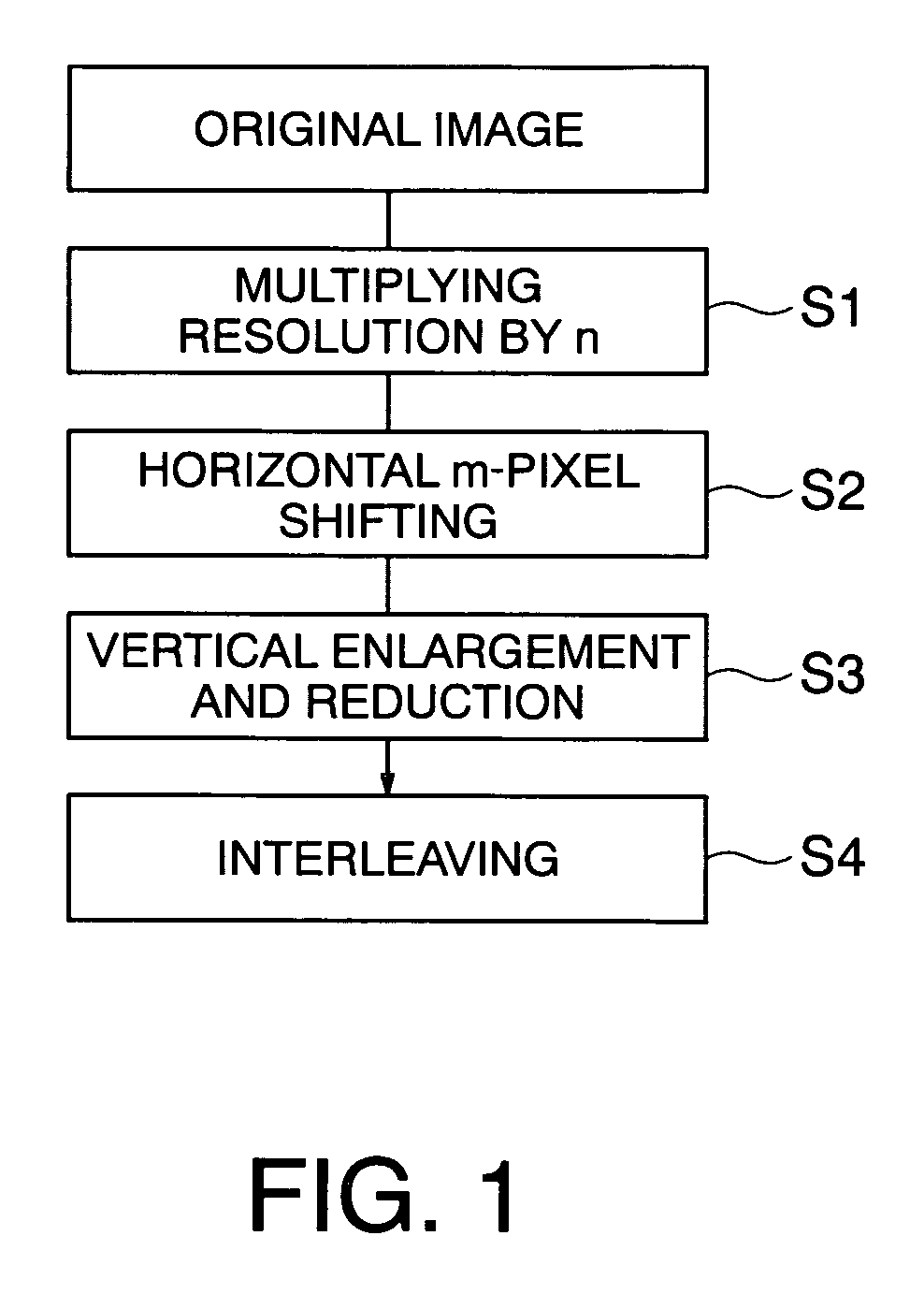
[0045] Referring to FIGS. 1 through 4, a producing method of an elemental image array for three-dimensional image display according to a first embodiment of the present invention will be described.

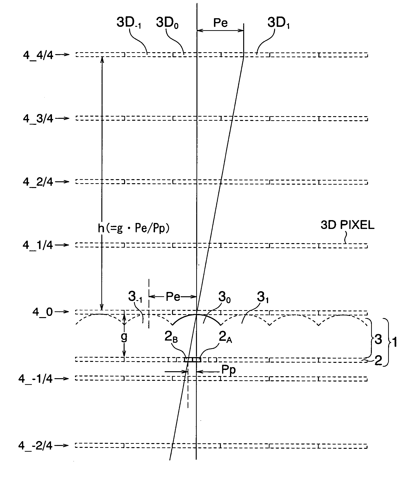
[0046] First, the principles of the producing method of an elemental image array for three-dimensional image display of this embodiment are described with reference to FIGS. 2 through 4(b).

[0047] The producing method of this embodiment is implemented in a three-dimensional image display device of a horizontal parallax type. FIG. 2 is a horizontal cross-sectional view of the horizontal-parallax three-dimensional image display device. This horizontal-parallax three-dimensional image display device 1 includes a two-dimensional image display device 2 that is formed with a liquid crystal panel, for example, and a light-ray control element 3 that is formed with a lenticular sheet having exit pupils, for example. The two-dimensional image display device 2 has pixels arranged t...

second embodiment

(Second Embodiment)

[0068] Referring now to FIGS. 5 through 15, an elemental image array producing device for three-dimensional image display according to a second embodiment of the present invention is described. The elemental image array producing device for three-dimensional image display according to this embodiment is a device in which the producing method of an elemental image array for three-dimensional image display according to the first embodiment is implemented. FIG. 5 shows the structure of the device. The elemental image array producing device of this embodiment includes an image processing unit 20, an image information rearranging processing unit 22, an elemental image array interleaving processing unit 24, a viewpoint image generating processing unit 26, a viewpoint image interleaving unit 28, and a rearranging processing unit 30.

[0069] A background adding processing unit 32 adds and combines a background image with the original image, based on original image informat...

third embodiment

(Third Embodiment)

[0081] Referring now to FIGS. 16 and 17, a producing program of an elemental image array for three-dimensional image display according to a third embodiment of the present invention is described. The producing program of this embodiment is a program for implementing the producing method of an elemental image array for three-dimensional image display according to the first embodiment. FIG. 16 and FIG. 17 are a perspective view and a block diagram showing one example of a computer system 130 that executes the producing program of this embodiment.

[0082] In FIG. 16, the computer system 130 includes a computer main body 131 having a CPU, a display device 132 such as a CRT, an input unit 133 such as a keyboard and a mouse, and a printer 134 for performing printing.

[0083] As shown in FIG. 17, the computer main body 131 has a built-in memory 135 configured by a RAM, and a memory unit 136 that can be provided inside or outside the main body 131. The memory unit 136 includ...


PUM


Abstract

A two-dimensional image can be displayed in a desired position, a desired aspect ratio of the display image can be maintained, and such an elemental image array as to maximize an interpolating effect can be produced. A producing method of an elemental image array for three-dimensional image display includes: converting the resolution of the two-dimensional image into substantially the same resolution of a three-dimensional image display device; obtaining multipoint images by shifting the position to sample the two-dimensional image after the resolution conversion at regular intervals in the horizontal direction; and rearranging the multipoint images according to the positional relationship between exit pupils and projecting directions.

Description

CROSS-REFERENCE TO RELATED APPLICATION [0001] This application is based upon and claims the benefit of priority from prior Japanese Patent Application Laid-open No. 2005-251394 filed on Aug. 31, 2005 in Japan, the entire contents of which are incorporated herein by reference.BACKGROUND OF THE INVENTION [0002] 1. Field of the Invention [0003] The present invention relates to a method, device, and producing program of an elemental image array for three-dimensional image display. [0004] 2. Related Art [0005] Parallax information that can be recognized by a viewer moving in a horizontal direction and viewing a two-dimensional image facing the viewer involves only horizontal movement of the two-dimensional image. If the two-dimensional image is located in front of the point of gaze, the two-dimensional image moves in the opposite direction from the viewer. If the two-dimensional image is located behind the point of gaze, the two-dimensional image moves in the same direction as the viewer...

Claims


Application Information

Patent Timeline
IPC IPC(8): G06T15/00G06T19/00H04N13/04
CPCH04N13/0404H04N13/0011H04N13/305H04N13/111
Inventor FUKUSHIMA, RIEKOTAKAGI, AYAKOSAISHU, TATSUOTAIRA, KAZUKIHIRAYAMA, YUZO
Owner KK TOSHIBA
Learn More