
Ablation catheter for setting a lesion

a technology of ablation catheter and lesion, which is applied in the field of ablation catheter for setting a lesion, can solve the problems of sustaining undesired irreparable injuries, a time-consuming and difficult process for producing linear lesion through ablation, and a patient's health risk that cannot be ignored

Inactive Publication Date: 2007-03-01
SIEMENS AG
View PDF11 Cites 123 Cited by
  • Summary
  • Abstract
  • Description
  • Claims
  • Application Information

AI Technical Summary

Benefits of technology

[0009] Greatly simplified ablating is facilitated thereby. The doctor is required simply to correctly position the catheter once; awkward traveling to the individual ablation locations, as was hitherto necessary, is totally dispensed with. Because the shape of the looped ablation section has been matched to the ablation area's three-dimensional shape, it is furthermore assured that the positional relationship will be precise and, consequently, that ablating can take place everywhere with the required intensity. The ultimate consequence of this is that ablating, and hence setting of the linear lesion, can be carried out much faster now that the complex handling operations involved in repeated catheter positioning are no longer required. For patients this means their treatment will be much quicker and less stressful; furthermore, a successful treatment can be achieved much more reliably because the difficulties described in the introduction will no longer exist owing to shape matching.
[0015] An especially advantageous embodiment of the invention provides for providing on the looped section, however formed, one or more electrodes for deriving electrophysiological signals over a signal lead on the catheter side. An intracardial ECG, for instance, can be derived via said measuring electrodes. The looped section's necessary wall contact can also be checked via these immediately prior to ablation, meaning, therefore, that correct positioning can also be checked electrophysiologically. The ablation section or the segments or the individual ablation elements can thus be activated precisely when the assigned electrodes or, as the case may be, signals received indicate a good wall contact.
[0020] As soon as the ablation element has assumed the 3D shape the section will be ducted under realtime imaging control and so placed in position exactly as provided when treatment was planned. It is for this purpose important for both the ablation section, or parts thereof, and all major anatomical structures, or parts thereof, such as, for example, the endocardium of the ventricle being treated, the ends of the pulmonary veins, high-risk areas etc., to be visualized together with the aid of realtime imaging. Two-dimensional x-ray monitoring or intracardial 2D or 3D ultrasound, or a combination of said imaging modalities, can be employed for realtime imaging. Pulmonary vein angiograms are advantageously produced when 2D x-ray imaging is used so that the ends of the pulmonary veins can be visualized and the shaped ablation wire placed in position relative to said ends of the pulmonary veins. Just prior to actual ablation, which is to say when correct positioning has taken place, the ablation section's correct positioning can be checked and, where applicable, corrected with the aid of, for instance, a final 3D C-arc x-ray rotation angiogram, also, where applicable, in conjunction with the signals registered via the measuring electrodes. It is also conceivable for the realtime image data mentioned to be overlaid with the pre-operatively recorded three-dimensional image data (from a CT examination, for example) used for planning. Said overlaying will make it possible to verify the ablation section's actual position relative to the planned lesion (contained in the pre-operatively recorded 3D image data as a result of marking by the electrophysiologist).

Problems solved by technology

Ablating in the vicinity of high-risk areas does, though, pose a risk for the patient that cannot be disregarded, namely of sustaining undesired irreparable injuries from said ablating.
Producing the linear lesion through ablation is also a very time-consuming process that is difficult to perform.
What is also problematic is carrying out respective local ablating to a sufficient extent; ensuring, that is to say, that the intracardial tissue will have been obliterated sufficiently to effect the desired electrical isolation in that area.
That is because owing to the patient-specific geometry of the atrioventricle or, as the case may be, irregular three-dimensional surface contours, and the fact that each point has to be traveled to separately with the ablation catheter, there is no assurance that the ablation catheter will in each instance be positioned correctly relative to the tissue or that the desired or, as the case may be, necessary degree of obliteration will be achieved during ablation.
As traveling to the correct, predetermined ablation location is also difficult, there is no assurance, either, that the individual ablation points will actually be set at the correct site and be spaced apart such as actually to produce complete isolation.
Albeit the ablation catheter's motion is continuously monitored during ablation, for example through x-ray monitoring, it is nevertheless extremely difficult to produce the lesion using the ablation catheter operating point-by-point.

Method used


Image

  • Ablation catheter for setting a lesion
  • Ablation catheter for setting a lesion
  • Ablation catheter for setting a lesion

Examples


Embodiment Construction

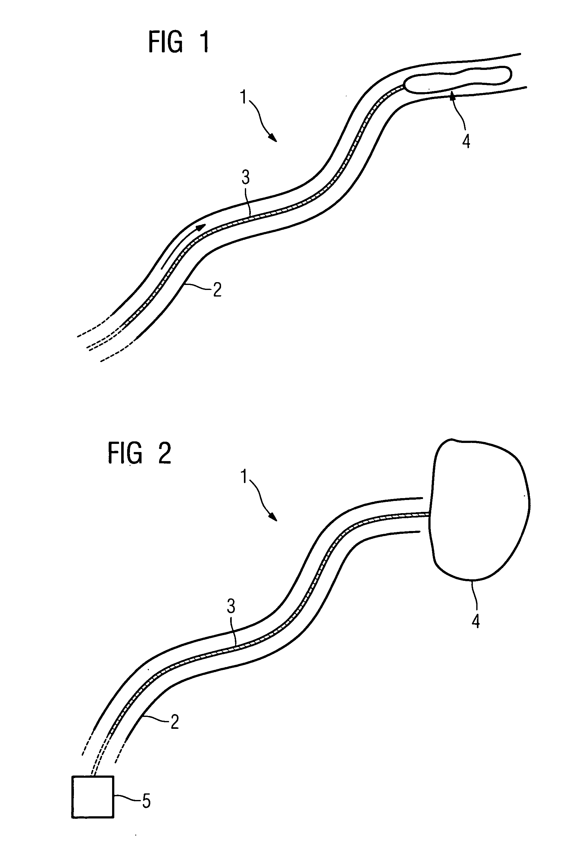
[0028]FIG. 1 shows schematically an inventive ablation catheter 1 consisting of the catheter sleeve 2 inside which is ducted a wire ablation element 3. Said ablation element 3 has on its front end a looped section 4 which, in the example shown, consists likewise of a thin wire. Said wire or, as the case may be, said section 4 can be folded so that it can be retracted inside the catheter sleeve 2.

[0029] The section 4 will be slid out of the catheter sleeve when the wire ablation element 3 is slid forward in the direction of the arrow shown in FIG. 1 after the catheter has been inserted into, for example, the ventricle. The resilient wire section 4 will unfold in the process and assume a closed shape imposed on it in advance, as shown in FIG. 2. Said shape will thus match as closely as possible that of the area of tissue on which ablating is to be performed, for instance the area around the pulmonary veins. That means the imposed shape of the wire section 4 can ultimately be of any k...


PUM


Abstract

Ablation catheter for setting a lesion, which catheter contains an ablation element that can be slid out of a catheter sleeve and has a looped section which, when said element is slid out, will self-expand into an automatically or manually imposed pre-specified shape corresponding to the actual shape of the area of tissue requiring to be ablated.

Description

CROSS REFERENCE TO RELATED APPLICATIONS [0001] This application claims priority of German application No. 10 2005 041 601.2 filed Sep. 1, 2005, which is incorporated by reference herein in its entirety. FIELD OF THE INVENTION [0002] The invention relates to an ablation catheter for setting a lesion. BACKGROUND OF THE INVENTION [0003] During electrophysiological procedures, one or more catheters are inserted into anatomical regions of the heart for the purpose of ablating, which is to say obliterating intracardial tissue. Ablation is performed with the aid of an ablation catheter and serves to permanently treat instances of arrhythmia. Ablating in the vicinity of high-risk areas does, though, pose a risk for the patient that cannot be disregarded, namely of sustaining undesired irreparable injuries from said ablating. So when ablation is performed on atrial fibrillation in the left atrioventricle, for example, the pulmonary veins leading into the left atrium are nowadays no longer is...

Claims


Application Information

Patent Timeline
IPC IPC(8): A61B18/14
CPCA61B18/1492A61B2018/1407A61B2018/0262A61B2018/00214
Inventor RAHN, NORBERT
Owner SIEMENS AG
Learn More