Image forming apparatus

Inactive Publication Date: 2007-03-01
PANASONIC CORP
View PDF18 Cites 7 Cited by
  • Summary
  • Abstract
  • Description
  • Claims
  • Application Information

AI Technical Summary

Benefits of technology

[0036] The present invention is made in view of the above circumstances of the conventional image forming apparatus. Thus, it is an object of the invention to provide an image forming apparatus which, when forming images on photo conductors by two or more light emitting elements arranged in a line in a main scanning direction, can prevent toner images to be formed from being strained and thus can provide high quality images at a reduced cost.
[0038] According to the image forming apparatus of the invention, toner images on the photo conductor can be formed in a linear manner, thereby being able to provide an image forming apparatus which can prevent the strained toner images, can be produced at a low cost and can provide high quality images.

Problems solved by technology

However, in the conventional image forming apparatus, the respective light emitting elements must be driven independently and thus, when the light emitting timings of all light emitting elements are made simultaneous, under the existing circumstances, the cost of the driver IC increases, which results in the increased cost of the exposure device.

Method used


Image

  • Image forming apparatus
  • Image forming apparatus
  • Image forming apparatus

Examples


embodiment 1

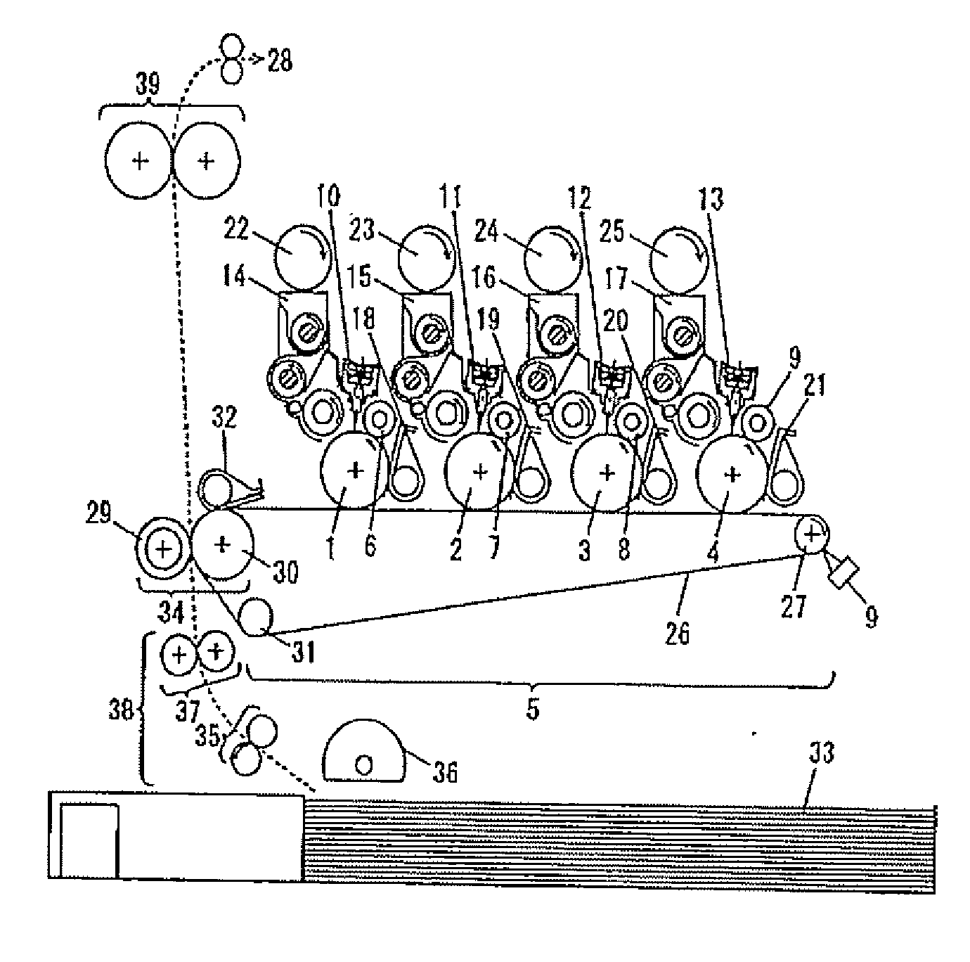
[0075]FIG. 1 is a schematic structure view of an image forming apparatus including two or more photo conductors according to an embodiment of the invention. The image forming apparatus according to the present embodiment comprises four photo conductors 1-4 and a transfer unit 5 which extends over these photo conductors. In the peripheries of the respective photo conductors 1-4, there are disposed charging devices 6-9, exposure devices 10-13 respectively acting as optical recording heads, developing devices 14-17, and photo conductor cleaning devices 18-21, respectively.

[0076] Developing agent storage parts 22-25 respectively store therein toners for colors respectively corresponding to the developing devices 14-17, and the toners stored therein are supplied to their associated developing devices 14-17 in such a manner that the densities of images to be recorded on paper can be made substantially constant.

[0077] The transfer unit 5 comprises a belt-shaped transfer member 26, a driv...

embodiment 2

[0115] Now, FIG. 9 is an explanatory view of a light emitting element array 62 for yellow employed in an embodiment 2 according to the invention. The composing elements, functions and operations of an image forming apparatus according to the embodiment 2 as well as the image forming method thereof are similar to the image forming apparatus according to the embodiment 1 shown in FIGS. 1-7, and thus the detailed description thereof is omitted here.

[0116] The structure of the light emitting element array 62 according to the embodiment 2 is almost similar to the structure of the embodiment 1 but these two embodiments are different from each other in the arrangement manner of the light emitting elements within the light emitting element blocks. Specifically, according to the embodiment 2, the light emitting elements in the central portions of the light emitting element blocks are arranged more downstream in the sub scanning moving direction of the photo conductor than the light emitting...

embodiment 3

[0122] Now, FIG. 10 is an explanatory view of a light emitting array 62 for yellow employed in an embodiment 3 according to the invention. The composing elements, functions and operations of an image forming apparatus according to the embodiment 3 as well as the image forming method thereof are similar to the image forming apparatus according to the embodiment 1 shown in FIGS. 1-7, and thus the detailed description thereof is omitted here.

[0123] The structure of the light emitting element array 62 according to the embodiment 3 is almost similar to the structure of the embodiment 1 but these two embodiments are different from each other in the arrangement manner of the light emitting elements within the light emitting element blocks. Specifically, according to the embodiment 3, the light emitting elements in the central portions of the light emitting element blocks not only are arranged more downstream in the moving direction of the photo conductor than the light emitting elements i...


PUM


Abstract

In an image forming apparatus, comprising: an optical recording head having a light emitting element array including two or more sets of light emitting element blocks arranged in a line in a main scanning direction, each block including a given number of light emitting elements arranged in a line in the main scanning direction; and, a photo conductor exposable by the light from the optical recording head, the light emitting elements of the light emitting element blocks each having a slow light emitting timing are arranged such that they are shifted downstream in the sub scanning moving direction of the photo conductor according to the light emitting timings thereof with respect to the light emitting elements each having a fast light emitting timing.

Description

BACKGROUND OF THE INVENTION [0001] 1. Field of the Invention [0002] The present invention relates to an image forming apparatus which uses an optical head including a light emitting element array as a light emitting source. [0003] 2. Description of the Related Art [0004] Recently, an image forming apparatus including a light emitting array as a light emitting source has been widely put to practical use. Especially, a color image forming apparatus having two or more photo conductors as image carriers (which is hereinafter referred to as an image forming apparatus simply) has been put to practical use together with a conventional image forming apparatus of a type in which a copy is obtained by two or more rotations (for example, by four rotations), because it has an advantage in the productivity of the image formation thereof. [0005] Now, FIG. 16 shows the schematic structure of a conventional image forming apparatus including two or more photo conductors. Specifically, this conventio...

Claims


Application Information

Patent Timeline
IPC IPC(8): B41J2/435
CPCB41J2/45
Inventor KAWANO, YUUZOUSUYAMA, KOUHEINISHIMURA, KAZUOSAKANOUE, KEINAKAMURA, TETSUROU
Owner PANASONIC CORP
Why Eureka
Try Eureka