
Inner casing of a rotating thermal machine

a technology of rotating thermal machines and inner casings, which is applied in the field of thermal machines, can solve the problems of adversely affecting efficiency and affecting the efficiency, and achieve the effects of reducing the requirement for space, reducing material consumption, and high degree of symmetry

Inactive Publication Date: 2007-03-01
GENERAL ELECTRIC TECH GMBH
View PDF18 Cites 2 Cited by
  • Summary
  • Abstract
  • Description
  • Claims
  • Application Information

AI Technical Summary

Benefits of technology

[0008] One aspect of the present invention includes providing an inner casing of a rotating thermal machine which avoids the disadvantages of known inner casings and is distinguished in particular by reduced consumption of material, reduced requirement for space and a high degree of symmetry while having a simple design.

Problems solved by technology

It is known that various problems may occur owing to the high temperatures occurring at the casing and the flanges which are screwed to one another: the casing is mechanically very rigid in the region of the flanges while it is comparatively weak at the poles which do not have flanges.
As a result, it is possible for oval deformations (in cross section) to occur, i.e., radial deformations which result in grinding of the tips of the blades which rotate in the interior against the casing walls or a large amount of play between the blade tip and the casing wall, which adversely affects the efficiency.

Method used


Image

  • Inner casing of a rotating thermal machine
  • Inner casing of a rotating thermal machine

Examples


Embodiment Construction

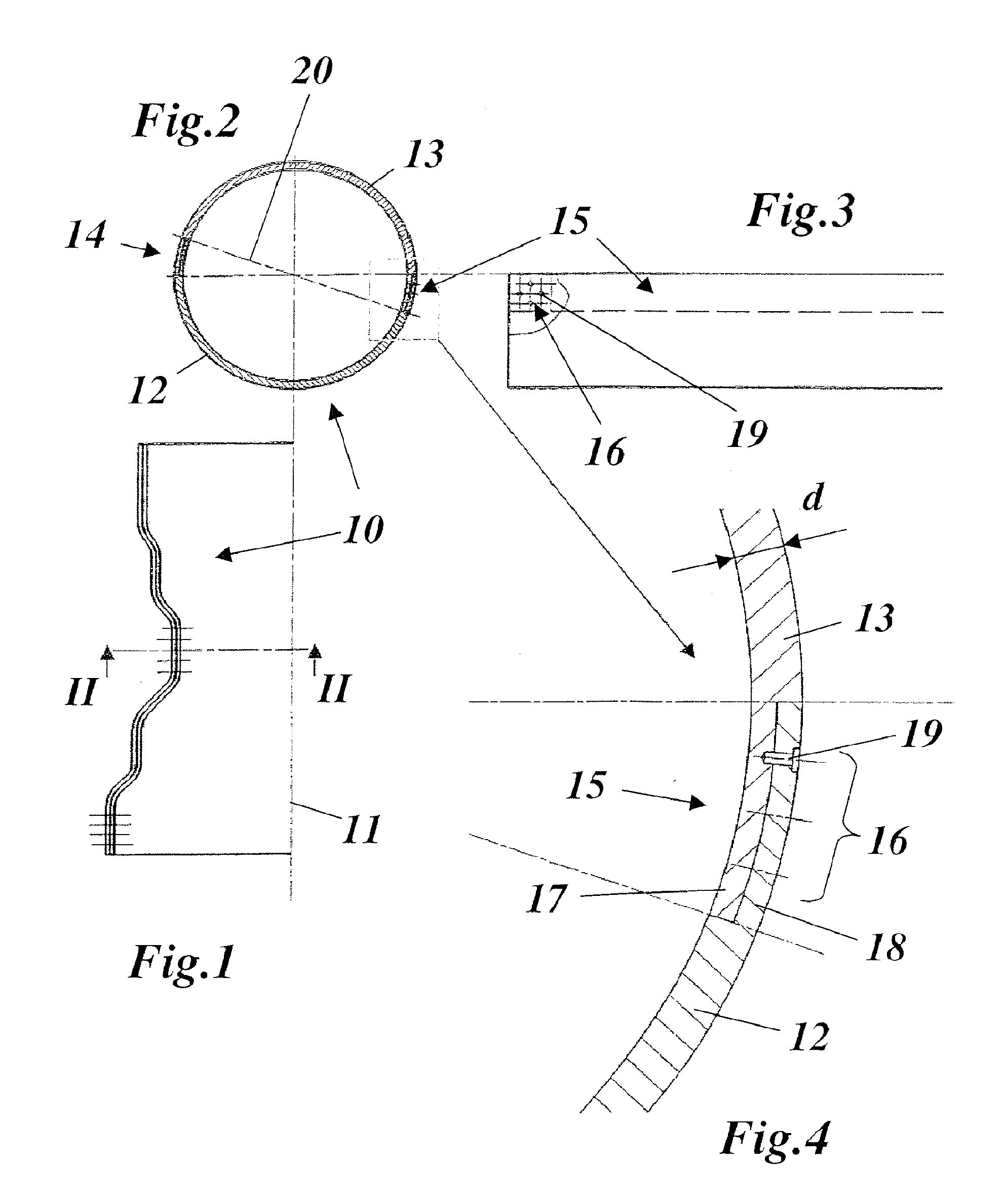
[0018] In FIG. 2, the cross section is represented by an inner casing 10 of a steam turbine according to an exemplary embodiment of the invention. The inner casing 10, which extends along an axis 11 and can have, for example, the diameter contour shown in FIG. 1 (for the medium pressure part of a two-channel steam turbine), is composed of an upper casing part 13 and a lower casing part 12. The two casing parts 12, 13 are assembled without the customary, laterally protruding flanges to form a virtually perfect, circular hollow cylinder, and are screwed to one another using a multiplicity of bolts 19 which are arranged in distributed fashion. The bolts 19 are orientated in the radial direction here.

[0019] For this purpose, the two casing parts 12 and 13 have, in the region of the parting plane 20, two overlapping areas 14, 15 which lie one opposite the other and in which the two casing parts 12, 13 overlap one another and are detachably connected to one another with overlapping secti...


PUM


Abstract

An inner casing (10) of a rotating thermal machine, in particular a steam turbine, has essentially the form of a hollow cylinder and is divided in a parting plane (20), which extends through an axis (11) of said casing, into a lower casing part (12) and an upper casing part (13), which casing parts (12, 13) are detachably connected to one another in the parting plane (20). The thermomechanical properties are improved with respect to casings provided with flanges in that the two casing parts (12, 13) have, in the region of the parting plane (20), two overlapping areas (14, 15) which lie opposite one another and in which the two casing parts (12, 13) overlap one another and are detachably connected to one another with overlapping sections (17, 18), in that the two casing parts (12, 13) have a predefined wall thickness (d), and in that the sum of the thicknesses of the overlapping sections (17, 18) is approximately the same as the wall thickness (d) of the two casing parts (12, 13) in the overlapping areas (14, 15).

Description

[0001] This application claims priority under 35 U.S.C. § 119 to Swiss application number 01382 / 05, filed 24 Aug. 2005, the entirety of which is incorporated by reference herein. BACKGROUND OF THE INVENTION [0002] 1. Field of the Invention [0003] The present invention relates to the field of thermal machines. It relates to an inner casing of a rotating thermal machine. [0004] 2. Brief Description of the Related Art [0005] Inner casings of a steam turbine are usually composed of two half shells, specifically an upper and a lower casing half which are screwed to one another in the horizontal parting plane by means of flanges which are arranged on the shells (see for example document U.S. Pat. No. B1-6,273,675). [0006] It is known that various problems may occur owing to the high temperatures occurring at the casing and the flanges which are screwed to one another: the casing is mechanically very rigid in the region of the flanges while it is comparatively weak at the poles which do no...

Claims


Application Information

Patent Timeline
Patent Type & Authority Applications(United States)
IPC IPC(8): F16L9/00
CPCF01D25/24F01D25/265F05B2260/301F05D2220/31F05D2250/231
Inventor KRIZ, DAVOR
Owner GENERAL ELECTRIC TECH GMBH
Learn More