
Moisture control system

a technology of moisture control and system, applied in the direction of building components, construction, building construction, etc., can solve the problems of moisture intrusion, contributing to possible condensation, and affecting the flow of water, so as to reduce the amount of mold growth, mildew growth, rot and/or pests, and facilitate the flow

Inactive Publication Date: 2007-03-01
HESS JAMIE P
View PDF21 Cites 53 Cited by
  • Summary
  • Abstract
  • Description
  • Claims
  • Application Information

AI Technical Summary

Benefits of technology

[0012] One advantage of the present invention is that the drainage channels of the moisture control device, according to the present invention, are inclined to utilize gravity to facilitate flow to prevent pooling, which reduces the amount of mold growth, mildew growth, rot and / or the presence of pests.
[0013] Another advantage of the present invention is that the positioning of the moisture channeling member, according to the present invention, permits the direct application of surface facing on the foundation portion of a wall because the moisture is directed to a drainage portion, which conveys the moisture to a location exterior to the wall system.

Problems solved by technology

Surface facings or cladding, such as stone veneer, stucco and brick suffer from the drawback that moisture may be present in an interior area of the wall system.
Damage to surface facing material may occur with little or no warning, causing moisture intrusion.
This incidental moisture may flow into the interior space of the wall or may contribute to the humidity of the air present in the interior space of the wall, eventually contributing to possible condensation.
If excess moisture is present within the wall from any or a combination of the above and / or the moisture is permitted to pool within the interior space of the wall, the presence of this moisture may lead to interior damage to the wall structure and / or building and promote the presence of pests, mold growth, mildew growth or rotting of the building materials.
These systems suffer from the drawback that the moisture control devices force the surface facings to terminate at the building / foundation interface in order to allow the moisture to exit from the inside of the surface facing.
The termination of the facing at the building / foundation interface in not aesthetically pleasing, because the termination provides a gap at the base of the wall at the foundation of the building / structure exposes a non-desirable facing material.
In addition, these systems only flow the moisture in the direction of gravity, wherein moisture may still pool in the interior spaces of the wall, especially at the lower portions of the wall at or near the interface between the interior wall structure and the foundation.
This approach suffers from the drawback that the horizontal installation allows pooling of the moisture, particularly between any weep holes, if present.
In addition, these structures are visible for the entire perimeter of the house, which is aesthetically undesirable.
In addition, it is undesirable to apply surface facing below this moisture control structure because the presence of surface facing would hinder the drainage of moisture and / or would undesirably be in contact with moisture.

Method used


Image

  • Moisture control system
  • Moisture control system
  • Moisture control system

Examples


Embodiment Construction

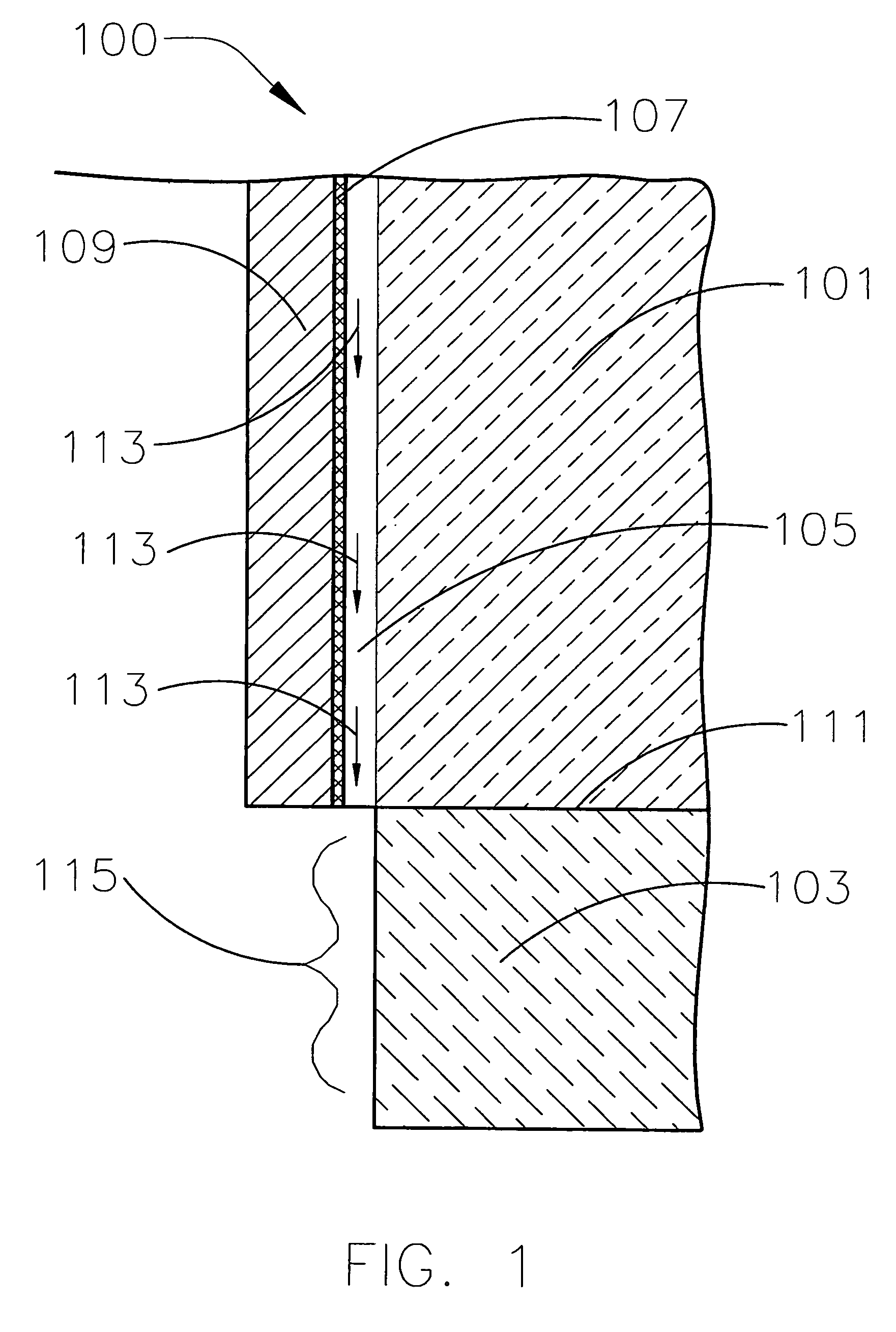
[0022]FIG. 1 shows a wall system having a known moisture drainage system. The wall system 100 includes an interior wall structure 101 disposed on a foundation 103. An interior cavity 105 is present between the interior wall structure 101 and a metal lath 107. The metal lath 107 may be present as a base for plaster or adhesive application, onto which a surface facing 109 may be applied. The surface facing 109 is applied to the metal lath 107. The surface facing 109 and metal lath 107 extend along the surface of the interior wall structure 101, but terminate at the interface 111 between the foundation 103 and the interior wall structure 101. Moisture formed or present in the interior cavity 105 flows in the direction of gravity toward the interface 111. The flow of moisture is shown in FIG. 1 as flow 113. The moisture is removed from the interior cavity 105 through the bottom of the interior cavity 105 and out of the wall system 100. This system suffers from the drawback that at least...


PUM


Abstract

The present invention includes moisture channeling member for removing moisture from the interior cavity of a surface facing system. The moisture channeling member includes a channel portion having a channel with an upper end, a lower end and a surface capable of conveying liquid. The channel is inclined at an angle with respect to level sufficient to facilitate flow of liquid from the upper end to the lower end. The channel portion is in fluid communication with an interior cavity of a surface facing system. A drainage portion is in fluid communication with the channel portion. The drainage portion is capable of consolidating and diverting moisture received from the channel portion and conveying the received moisture to an exterior area of the surface facing system.

Description

FIELD OF THE INVENTION [0001] The present invention is directed to moisture control systems for controlling moisture in surface facing systems on building structures. BACKGROUND OF THE INVENTION [0002] Surface facings or cladding, such as stone veneer, stucco and brick suffer from the drawback that moisture may be present in an interior area of the wall system. This moisture may originate from a variety of sources, including leakage through damage to the surface facing, condensation within the interior area or incidental moisture present from the building materials making up the wall system. Damage to surface facing material may occur with little or no warning, causing moisture intrusion. Condensation may form on the rear or backside of surfacing materials or other surfaces within the interior wall space. Under certain atmospheric conditions, water can condense on the backside of the panels even where there is no compromise of the surface facing. The extent of condensation varies wi...

Claims


Application Information

Patent Timeline
Patent Type & Authority Applications(United States)
IPC IPC(8): E04B1/70
CPCE04B1/7046E04F17/00
Inventor HESS, JAMIE P.
Owner HESS JAMIE P
Learn More