Screw rotor and vacuum pump

a screw rotor and vacuum pump technology, applied in the field of screw rotors, can solve the problems of difficult machining, high cost due to complicated machining, and constant change of profile shape, and achieve the effects of shortening the rotor length, increasing the discharge efficiency, and low cos

Inactive Publication Date: 2007-02-22
KASHIYAMA IND
View PDF6 Cites 5 Cited by
  • Summary
  • Abstract
  • Description
  • Claims
  • Application Information

AI Technical Summary

Benefits of technology

[0016] In aspect 2 of the invention, a vacuum pump is characterized by including the screw rotor in aspect 1 or form 1 of aspect 1. Since the vacuum pump comprising the components in aspect 2 has the same screw rotors as that in aspect 1 or form 1 of aspect 1, it has the same effect as aspect 1 or form 1 of aspect 1.
[0017] The foregoing described invention makes it possible to provide a screw rotor that is capable of compressing gas at low cost. Moreover, it is capable of increasing the discharge efficiency as well as shortening the rotor length.

Problems solved by technology

However, in the case of continuously variable pitch design, a high cost due to complicated machining is regarded as a problem.
However, since the intermesh interference between the threads becomes large with large lead size, it is required that the profile shape changes continuously with continuously variable pitch.
In the case of continuously variable pitch of a thread, failure to carry out thread machining with one end-mill resulting in difficult machining and high cost.
However, the discontinuous change of discharge volume between the rotor of a large thread lead and the rotor of a small thread lead results in low discharge efficiency.
If bearings are mounted at the vacuum side, it becomes necessary to provide lubricant for the bearings; furthermore, measures should be taken to prevent pollution to the vacuum chamber resulting in a complicated structure and high cost.

Method used


Image

  • Screw rotor and vacuum pump
  • Screw rotor and vacuum pump
  • Screw rotor and vacuum pump

Examples


embodiment 1

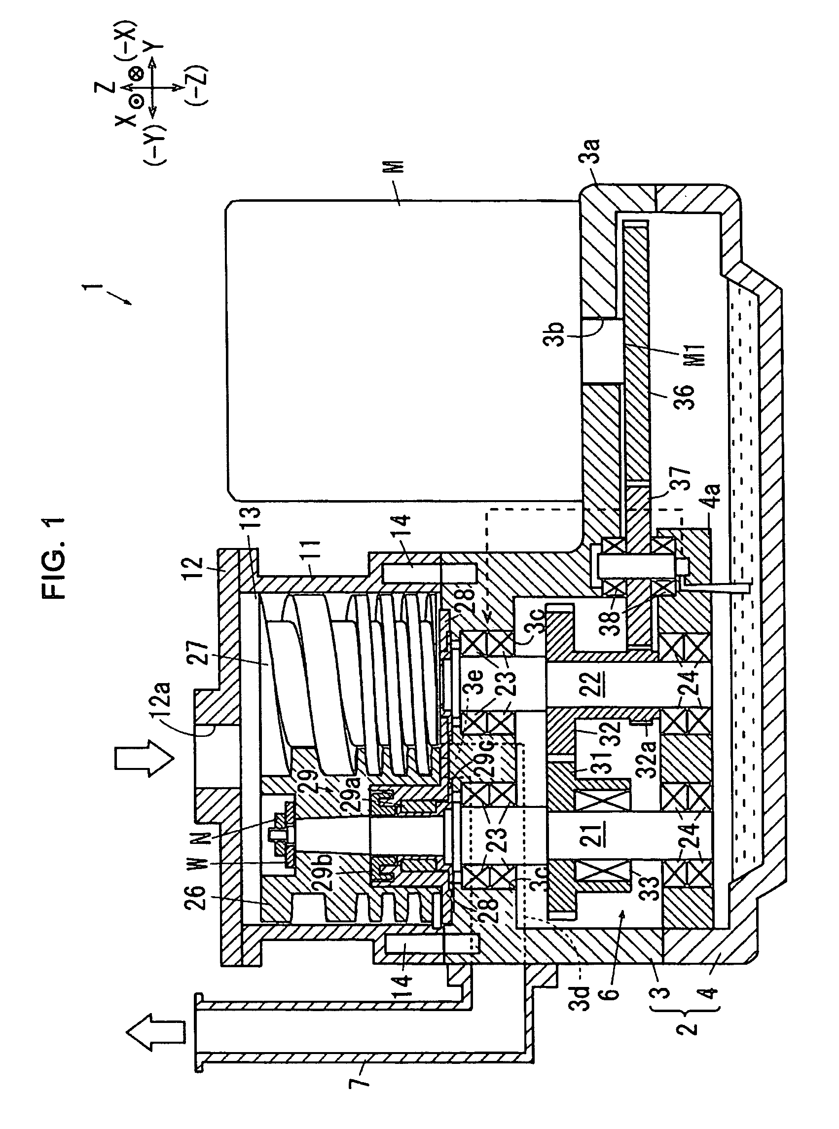
[0039] Embodiment 1 of the invention is further explained as follows. FIG. 1 is an overall illustration of a screw type dry vacuum pump. It shows in FIG. 1 that there is a base 2 mounted in the screw type dry vacuum pump 1 in the invention. The upper base 3 and lower base 4 are mounted on base 2, with a gear room 6 designed within base 3 and base 4. On the right side of base 2, motor stand 3a to support pump motor M is mounted. A motor shaft through-hole 3b is drilled on motor stand 3a for motor shaft M1 to go through. On the left side of the upper end of upper base 3, a pair of upper bearing saddles 3c is mounted. On the left side of upper base 3, discharge duct 7 is fixed, with which the downstream end of discharge passage 3d formed within base 3 is connected. Discharge outlet 3e is formed on the upstream end of discharge passage 3d. On the upper end of the left side of lower base 4, lower bearing saddle 4a is mounted. Lubricant for bearing lubrication is stored at the bottom of l...

embodiment 2

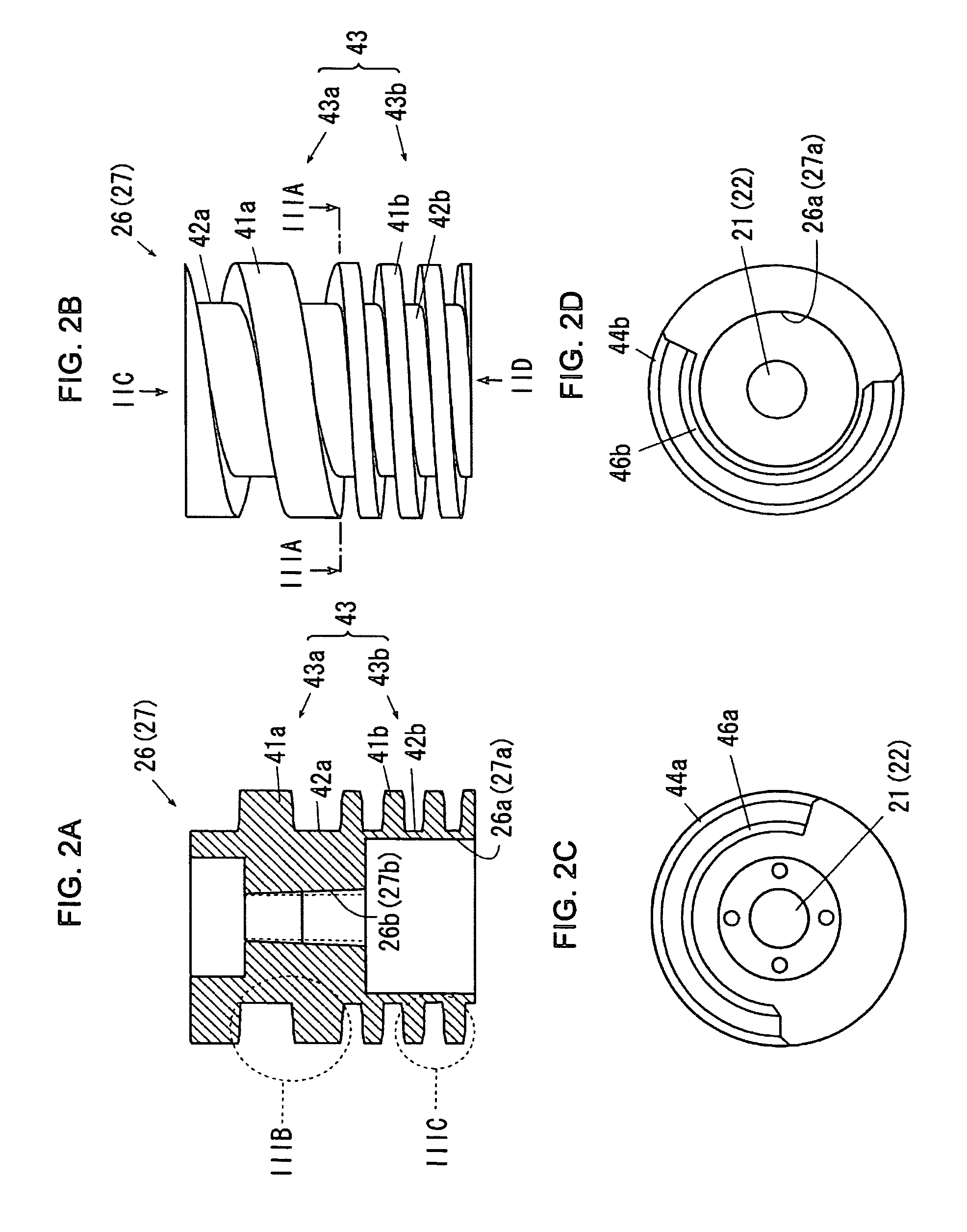
[0057] Embodiment 2 of the invention is further explained as follows. FIG. 5 is an overall illustration of screw type vacuum pump in embodiment 2, corresponding to FIG. 1 embodiment 1. FIG. 6 illustrates screw rotor in embodiment 2 corresponding to FIG. 2 of embodiment 1. FIG. 6A is a sectional view. FIG. 6B is a side view. FIG. 6C is a sectional view taken from arrow VIC FIG. 6B. FIG. 6D is a sectional view taken from arrow VID of FIG. 6B. FIG. 6E shows an enlarged illustration of VIE section in FIG. 6A.

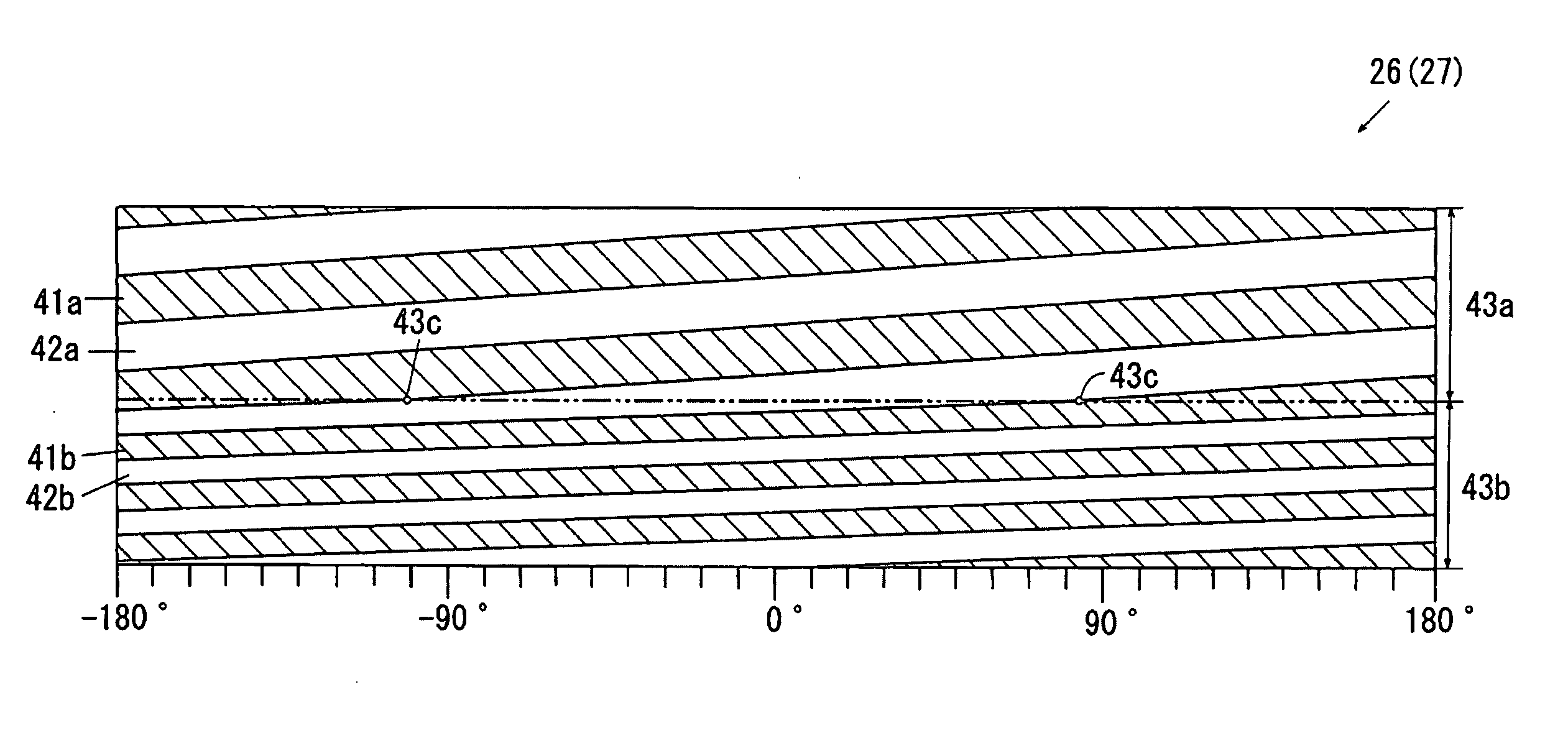
[0058]FIG. 7 is the expanded view of the screw rotor profile in embodiment 2, corresponding to FIG. 4 in embodiment 1. Additionally, regarding the illustration of embodiment 2, same symbols for the corresponding components are used as in embodiment 1 whith specific explanation of the symbols omitted. Regarding the components of embodiment 2, it is the same as those of embodiment 1 except the following features.

[0059] As shown in FIG. 5 to FIG. 7, screw type vacuum pump 1 of embodim...


PUM


Abstract

The invention provides a low-cost screw rotor that is capable of compressing gas. As exemplified in FIG. 4, screw rotors (26, 27) comprise: upstream screw section (43a) defined on the upstream side of the gas travel path with screw thread (41a) identically positioned at the same interval, and downstream screw section (43b) connecting to the downstream side of upstream screw section (43a) along the gas travel path, where threads (41b) on the downstream screw section are arranged continuously with identical pitch smaller than threads (41a) on the upstream screw section; and the upstream end of the downstream screw thread (41b) along the gas travel path and the downstream end of upstream screw thread (41a) along the gas travel path are continuously connected at a yielding point (43c).

Description

TECHNICAL FIELD [0001] The invention relates to a screw rotor having a threaded outer periphery and a screw-type vacuum pump equipped with a pair of the screw rotors. In particular, the invention relates to a screw rotor that is capable of compressing gas during transportation of gas, and a vacuum pump equipped with the screw rotors. BACKGROUND [0002] With respect to a vacuum pump that discharges gas from a vacuum chamber, a screw type vacuum pump that transports and discharges gas by means of rotation of jogged screw rotors having threaded outer periphery is well known. As an example, the herein described screw type dry vacuum pump applying traditional technology (J01) is well-known. (J01) Prior art is described in Patent document 1 (Japanese Patent Laid-open Publication No. 2000-45976) [0003] As described in Patent document 1, a screw-type dry vacuum pump comprises a pair of screw rotors having square thread on the outer periphery with identical lead (distance that a screw thread ...

Claims


Application Information

Patent Timeline
Patent Type & Authority Applications(United States)
IPC IPC(8): F01C1/16F04C2/00F01C1/24F04C18/00F03C2/00
CPCF04C18/084F04C18/16F04C2220/10
Inventor OZAWA, OSAMUICHIKAWA, TAKESHIMATUDA, SHINICHI
Owner KASHIYAMA IND
Why Eureka
Try Eureka