Method and system for determining a sharp panoramic image constructed from a group of projection images

Inactive Publication Date: 2007-02-22
PALODEX GROUP
View PDF10 Cites 5 Cited by
  • Summary
  • Abstract
  • Description
  • Claims
  • Application Information

AI Technical Summary

Benefits of technology

[0005] The object of the invention is to provide a method and system to determine an arbitrary sharp panoramic Image layer in an image constructed from a group of projection images, where the desired layer for the panoramic image can be determined after obtaining projection image data of the object, and furthermore to allow the positioning of the object to be determined more freely and still obtain sharp panoramic layer images. Especially the object of the invention is to allow generate numbers of sharp panoramic image layers from data obtained from the object by only one shot.

Problems solved by technology

The point is that F gives high penalty for panoramic images that do not show clearly the desired diagnostic information.

Method used


Image

  • Method and system for determining a sharp panoramic image constructed from a group of projection images
  • Method and system for determining a sharp panoramic image constructed from a group of projection images
  • Method and system for determining a sharp panoramic image constructed from a group of projection images

Examples


Embodiment Construction

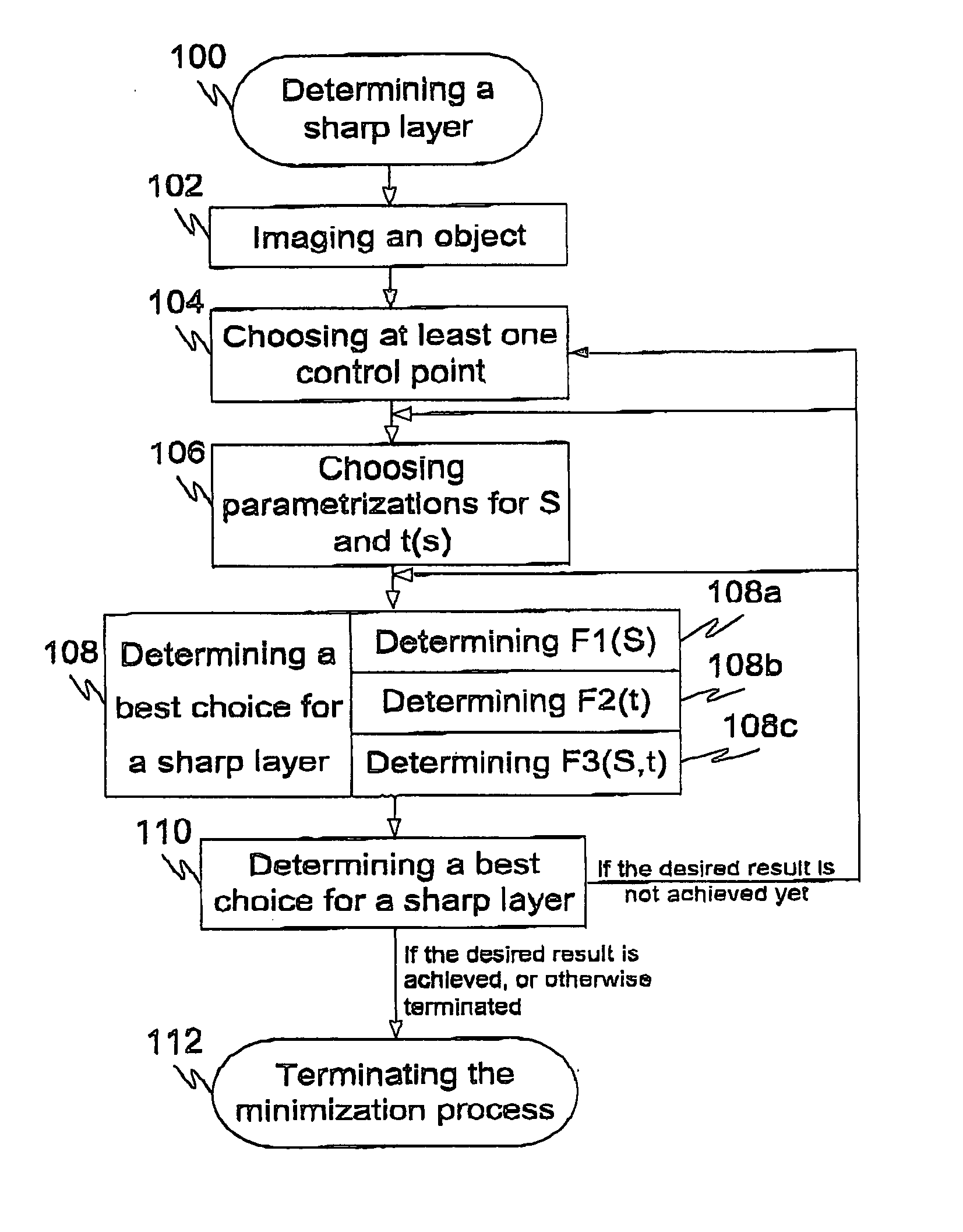
[0096]FIG. 1 illustrates a flow diagram of an exemplary method 100 for determining a sharp panoramic image layer constructed from a group of projection images according to an advantageous embodiment of the present invention, where at step 102 an object to be determined is imaged and numbers of projection images are obtained. Next at step 104 control points, or at least one control point, are chosen, and at step 106 parameterizations for a surface S and thickness function t(s) are chosen. Typically the points are located inside the dental arch, so that the distance between neighbouring points is typically between 10 mm-50 mm but it is not restricted to this distance scala.

[0097] Once the parameterizations of S and t(s) are chosen, the first best choice for a center surface of a sharp layer is determined at step 108 by defining a penalty function F(S,t), where F(S,t)=F1 (S)+F2(t)+F3(S,t), for example. At step 108 the components of F(S,t), in other words F1(S), F2(t) and F3(S,t) are d...


PUM


Abstract

The invention relates to a method and system for determining a sharp panoramic image constructed from a group of projection images, especially the invention relates to defining a structure of the panoramic X-ray image of an area of a dentition and of jaws. The structure of a panoramic image to be generated from a group of projection images is determined by at least two crucial parameters, namely parameters of the central surface S of the sharp layer and thickness t(s) of the sharp layer, using penalty function F(S,t), which is at least a penalty function F3(S,t) of low-frequency changes in the computed panoramic image corresponding to the choices S and t(S). After computing F3(S,t) the best center surface and thickness function (in other words the sharpest layer of the panoramic image) is obtained by minimizing said penalty function F(S,t) over parameter space.

Description

TECHNICAL FIELD OF THE INVENTION [0001] The invention relates to a method and system for determining a sharp panoramic image constructed from a group of projection images. Especially the invention relates to defining a structure of the panoramic X-ray image of an area of a dentition and of jaws. BACKGROUND OF THE INVENTION [0002] Extra oral / panoramic dental imaging is nowadays a very common practise in a medical treatment of patients. Typical X-ray apparatus used for extra oral / panoramic dental imaging includes a rotative arm suspended at one end of a support column and an X-ray generating device and an X-ray detecting device (C-arm) oppositely fixed to respective ends of the rotative arm. The X-ray detecting device (C-arm) is typically a film-based device or CCD-based (Charged Coupled Device) device. The X-ray exposure is performed with rotation of the arm so that the movements of the rotative arm and thus also movements of the X-ray generating device and the X-ray detecting device...

Claims


Application Information

Patent Timeline
IPC IPC(8): H05G1/60A61B6/00
CPCA61B6/14G06T3/4038G06T2207/30036G06T2207/10116G06T2207/20221G06T5/50A61B6/51G03B37/00G06T7/40A61B6/00
Inventor SILTANEN, SAMULIKALKE, MARTTISETALA, HENRISUURONEN, ESA
Owner PALODEX GROUP
Why Eureka
Try Eureka