
Plasma display panel power recovery method and apparatus

a technology of power recovery circuit and plasma display panel, which is applied in the direction of electronic switching, pulse technique, instruments, etc., can solve the problems of electromagnetic interference (emi), damage to the switch, and it is extremely difficult for a conventional power recovery circuit to recover 100% of energy, so as to improve the power recovery efficiency of a power recovery circuit coupled to the discharge electrode of the plasma display panel.

Inactive Publication Date: 2007-02-22
SAMSUNG SDI CO LTD
View PDF2 Cites 3 Cited by
  • Summary
  • Abstract
  • Description
  • Claims
  • Application Information

AI Technical Summary

Benefits of technology

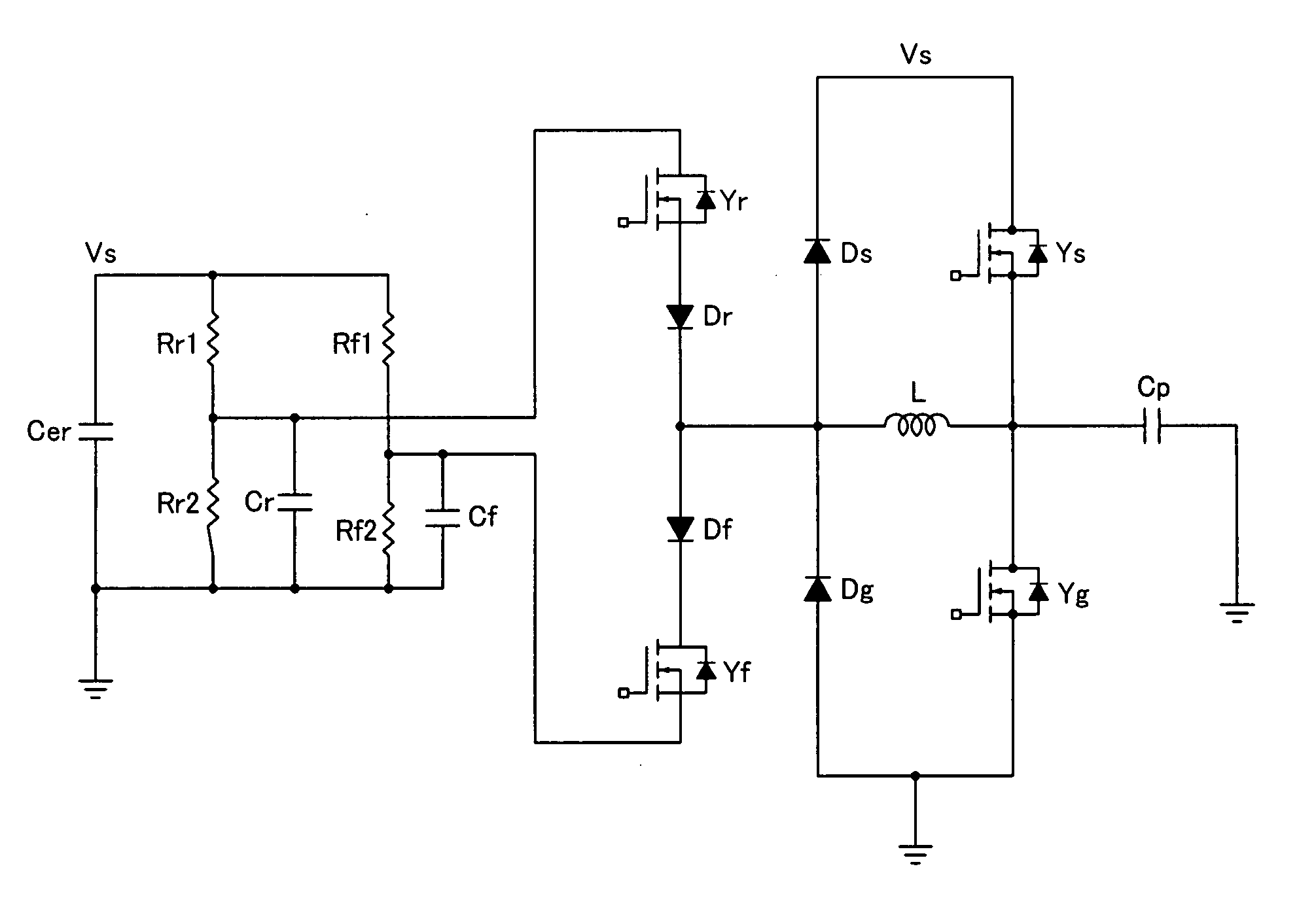
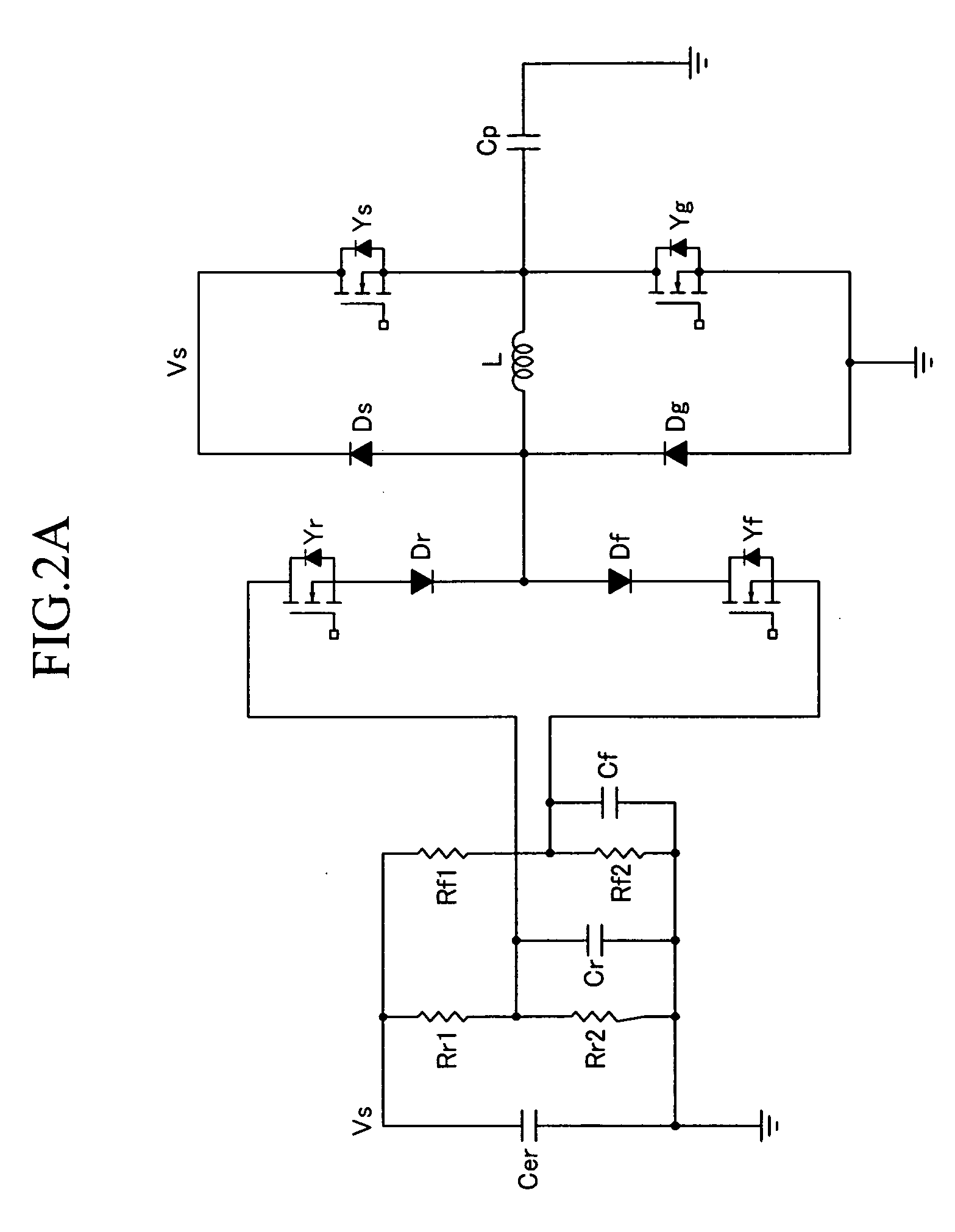
[0006] In accordance with the present invention, the power recovery efficiency of a power recovery circuit coupled to sustain discharge electrodes of a plasma display panel is improved. A voltage of a first power recovery capacitor in the power recovery circuit is set to be greater than half of a sustain discharge voltage when a voltage of the power recovery circuit applied to the sustain discharge electrodes is increased, and a voltage of a second power recovery capacitor in the power recovery circuit is set to be lower than half of the sustain discharge voltage when the voltage of the power recovery circuit applied to the sustain discharge electrodes is decreased, the first power recovery capacitor and the second power recovery capacitor both being coupled to the sustain discharge electrodes.

Problems solved by technology

However, it becomes extremely difficult for a conventional power recovery circuit to recover 100% of energy because a switch and the circuit may cause losses while recovering power, and accordingly a sustain discharge voltage cannot be increased to a high level voltage of the sustain discharge pulse or cannot be decreased to a low level voltage of the same during a power recovery operation.
When the switch that supplies the high level voltage or the low level voltage of the sustain discharge pulse is turned on in this state, the switch may be hard-switched thereby causing damage to the switch as well as causing electromagnetic interference (EMI).

Method used


Image

  • Plasma display panel power recovery method and apparatus
  • Plasma display panel power recovery method and apparatus
  • Plasma display panel power recovery method and apparatus

Examples


Embodiment Construction

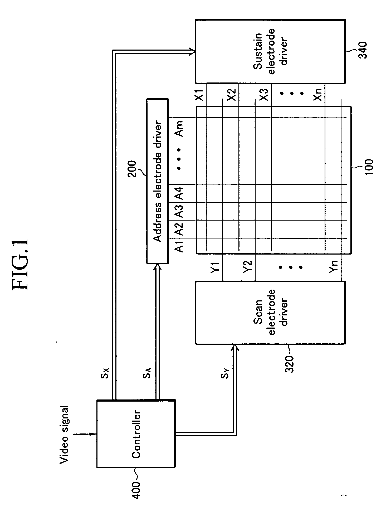
[0014] Referring to FIG. 1, a plasma display device includes a PDP 100, an address electrode driver 200, a scan electrode driver 320, a sustain electrode driver 340, and a controller 400.

[0015] The PDP 100 includes a plurality of address electrodes Al to Am extending in a column direction, and a plurality of sustain and scan electrodes Xl to Xn and Y1 to Yn extending in a row direction by pairs. Hereinafter, the address electrode is referred to as an A electrode, the sustain electrode is referred to as a Y electrode, and the scan electrode is referred to as an X electrode.

[0016] The address electrode driver 200 receives an address driving control signal SA from the controller 200, and applies a display data signal to the respective A electrodes to select a discharge cell to be displayed.

[0017] The scan electrode driver 320 and the sustain electrode driver 340 respectively receive a scan electrode driving signal Sy and a sustain electrode driving signal Sx from the controller 200,...


PUM


Abstract

In the plasma display device, a voltage of a power recovery capacitor is set to be greater than half of a sustain discharge voltage when a voltage of a power recovery circuit is increased, and is set to be lower than half of the sustain discharge voltage when the voltage of the power recovery circuit is decreased. Accordingly, power recovery efficiency can be improved.

Description

CROSS-REFERENCE TO RELATED APPLICATION [0001] This application claims priority to and the benefit of Korean Patent Application No. 10-2005-0075166 filed in the Korean Intellectual Property Office on Aug. 17, 2005, the entire content of which is incorporated herein by reference. BACKGROUND [0002] The present invention relates to a plasma display device and a driving method thereof. More particularly, the present invention relates to a power recovery circuit of a plasma display device. [0003] A plasma display. device is a flat panel display that uses plasma generated by a gas discharge to display characters or images. It includes a plasma display panel (PDP) wherein tens to millions of pixels are provided in a matrix format, depending on its size. [0004] When one PDP electrode is applied with a sustain discharge pulse and another electrode operates as a capacitive load additional reactive power is needed as well as power for a sustain discharge in order to apply a sustain pulse to the...

Claims


Application Information

Patent Timeline
IPC IPC(8): G09G3/28G09G3/288G09G3/20G09G3/296G09G3/298H03K17/16H03K17/695
CPCG09G3/293G09G3/294G09G3/2965G09G2330/06G09G3/296
Inventor LEE, DONG-MYUNG
Owner SAMSUNG SDI CO LTD
Learn More