Dual filtration lateral flow containment enclosure

a technology of lateral flow and containment enclosure, which is applied in the direction of isotope separation, dispersed particle separation, hazardous material storage, etc., can solve the problems of compromising product protection, contaminated air continuously entering the enclosure, and breaching the containment of hazardous materials, so as to prolong the life of the filtration arrangement, prevent the build-up of chemical fumes, and save the cost and space of purchasing and installing

Inactive Publication Date: 2007-02-22
AIREY THOMAS DEAN
View PDF4 Cites 43 Cited by
  • Summary
  • Abstract
  • Description
  • Claims
  • Application Information

AI Technical Summary

Benefits of technology

[0008] 1) To provide product protection by preventing contaminants in the ambient air from entering the enclosure. In many cases contaminants such as bacteria, mold spores, dust, environmental pollutants, etc. will interfere with the sample or with the protocol being undertaken and must be prevented from entering the enclosure.
[0031] The optimized design and non-recirculating lateral arrangement of the airflow discussed above, and the optimized non-recirculating vertical arrangement of the airflow discussed above, allows the enclosure to maintain product protection and containment capacities even when the power or air handling systems fail. This is accomplished by not having any unnecessary ducting and / or unfiltered open portals to the environment. Such ducting and openings exist in traditional BSCs and in lateral airflow adaptations of traditional BSCs and produce serious safety deficiencies.

Problems solved by technology

If airflow fails for any reason, hazardous material containment is breached as the enclosure becomes open to the environment (compromising personnel, product, and environmental protection).
Even under normal operating conditions, high volumes of unfiltered, contaminated air continuously enter the enclosure and compromise product protection.
Of even greater concern is the fact that the enclosure does not provide complete containment of hazardous materials.
Any disruption in the airflow due to the movement of a worker's hands, equipment obstruction, heat currents, room air currents, and the like can cause small amounts of the air inside of the enclosure to escape containment.
Unnecessary ducting and recirculating of airflow increases energy consumption, manufacture costs and complexity, space requirements, difficulty in maintenance and decontamination, and increases noise production.

Method used


Image

  • Dual filtration lateral flow containment enclosure
  • Dual filtration lateral flow containment enclosure
  • Dual filtration lateral flow containment enclosure

Examples


Embodiment Construction

[0046] Unless defined otherwise, all technical and scientific terms used herein have the same meaning as commonly understood by one of ordinary skill in the art to which the invention belongs. Although any methods and materials similar or equivalent to those described herein can be used in the practice or testing of the present invention, the preferred methods and materials are now described. All publications mentioned hereunder are incorporated herein by reference.

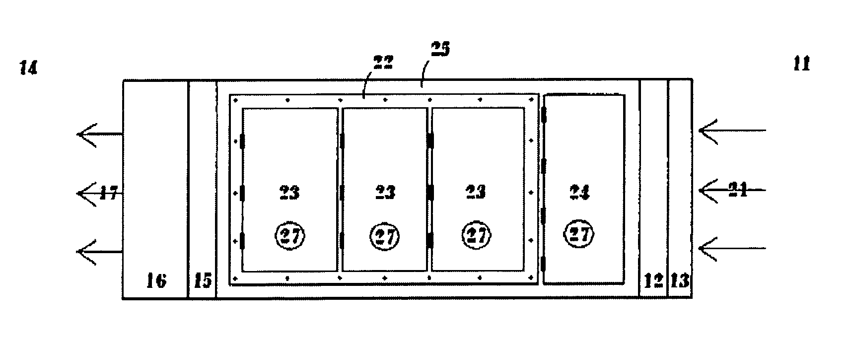
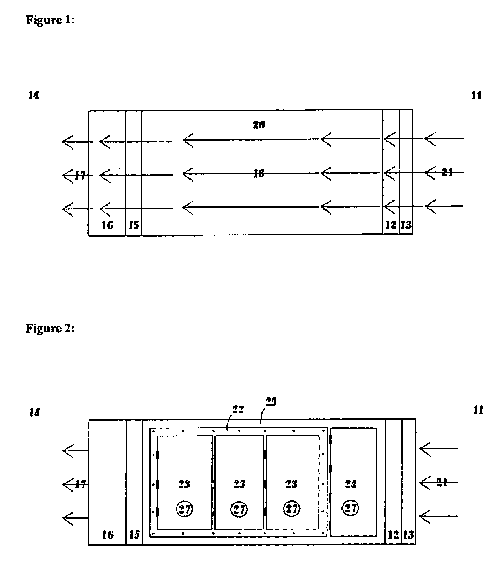
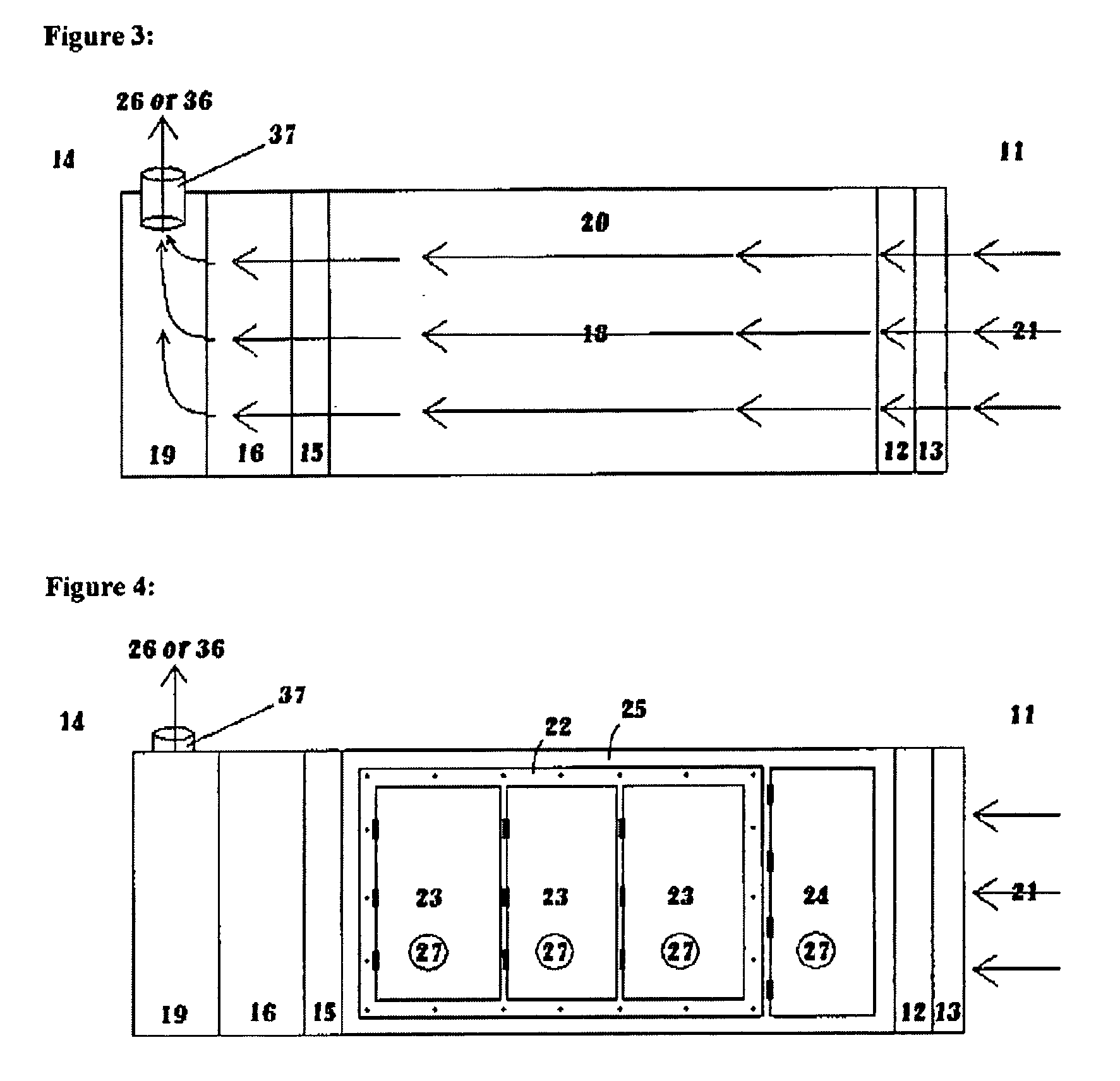
[0047] When working with hazardous materials, institutions (such as laboratories, hospitals, and government agencies) must provide protection for their personnel, the environment, and often for the products that they are working with. The invention described herein is a containment solution for the safe manipulation of hazardous materials. This invention was specifically created to meet the need for an enclosure that efficiently provides the highest possible levels of personnel, product, and environmental protection in a...


PUM


Abstract

A dual filtration lateral flow containment enclosure is described wherein an air evacuation system is used to provide negative airflow between an upstream filtration system and a downstream filtration system. The enclosure may be arranged such that there is no unfiltered venting between the environment and the interior of the enclosure if so desired. Furthermore, the filtration systems are arranged for the insertion of multiple types of filters, for example, HEPA filters, chemical filters, biological filters and the like for specific removal of air-borne materials from the air flow.

Description

PRIOR APPLICATION INFORMATION [0001] This application claims the benefit of U.S. Provisional Patent Application 60 / 695,449, filed Jul. 1, 2005 and U.S. Provisional Patent Application 60 / 719,220, filed Sep. 22, 2005.FIELD OF THE INVENTION [0002] This invention pertains to the field of hazardous materials containment systems and workspaces, and to the field of enhancing dispersed rapid response capacities to hazardous materials incidents (including the transport, treatment, and quarantine of material and casualties of hazardous materials incidents). The invention may be adapted for use with biological, chemical, toxicological, and radioactive materials BACKGROUND OF THE INVENTION [0003] The present invention maintains its containment and product protection capacities even if its power or air handling systems fail. Traditional fume hoods, class I and class II biological safety cabinets (BSCs), and current lateral airflow designs that are adaptations of such BSCs rely upon airflow to pr...

Claims


Application Information

Patent Timeline
IPC IPC(8): B01D50/00
CPCB01L1/50B01L1/04
Inventor AIREY, THOMAS DEAN
Owner AIREY THOMAS DEAN
Why Eureka
Try Eureka