
Tubular implantable sling and related delivery systems, methods and devices

a technology of slings and tubes, applied in the field of surgically implantable supportive slings, can solve the problems of patients' pain for weeks, insufficient response time, urine to leak out of the urethra during stressful activities, etc., and achieve the effects of improving the patient's comfort, reducing pain, and increasing length

Active Publication Date: 2007-02-15
BOSTON SCI SCIMED INC
View PDF42 Cites 65 Cited by
  • Summary
  • Abstract
  • Description
  • Claims
  • Application Information

AI Technical Summary

Benefits of technology

[0005] The invention addresses the deficiencies of the prior art by providing improved devices, systems and methods relating to an implantable sling for supporting an anatomical site in the body of a patient. More particularly, in various embodiments, the invention provides a supportive sling that can be inserted into the body of a patient in a low width state, and subsequent to insertion into the body, can be reconfigured to have a larger width sized appropriately for supporting the anatomical site. According to one embodiment, in the low width state, the sling has an increased length. As the length is decreased subsequent to insertion, the width increases. According to one advantage, the sling can be transitioned from between the first and second states without damaging the sling. According to another advantage, the transitioning between the first and second states also provides a mechanism for tensioning the sling under the anatomical site being supported. The sling of the invention may be used to support any suitable internal anatomical site. However, in some embodiments, the sling of the invention may be employed, for example, for providing a urethral support to treat urinary incontinence or for pelvic floor reconstruction.
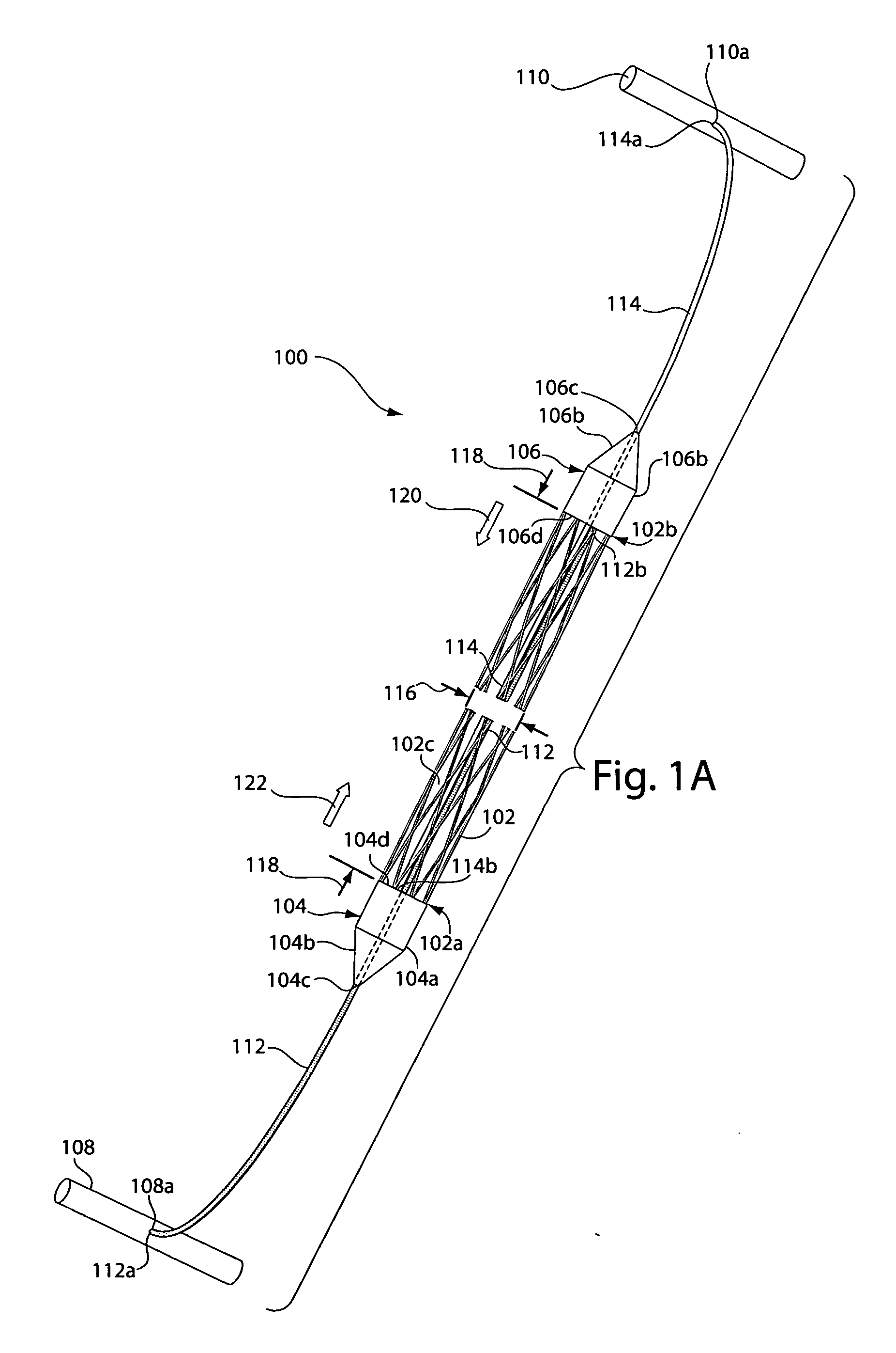
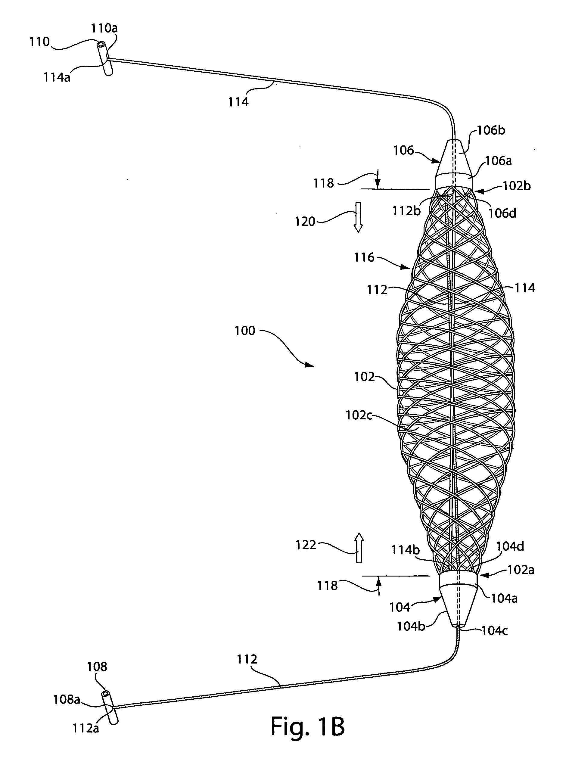
[0009] In operation, pulling on a terminal end of the first tensioning filament while holding a terminal end of the second tensioning filament stationary draws the first end cap axially along the second tensioning filament to effectively shorten the length of the sling. Due to the tubular configuration of the sling, this pulling also causes the width of the sling along at least a middle portion to widen. Similarly, pulling on the terminal end of the second tensioning filament while holding the terminal end of the first tensioning filament stationary draws the second end cap axially along the first tensioning filament, once again to effectively shorten the length and increase the width of the sling.
[0010] The sling of the sling assembly may be made of any suitable material. However, in preferred embodiments, the sling is formed from a woven or mesh material. The woven or mesh material enables the sling to transition easily between various lengths and widths as described above, without twisting, folding or otherwise becoming tangled, damaged or undesirably distorted.
[0021] A further aspect of the invention provides a method for treating urinary incontinence or for pelvic floor reconstruction. According to one embodiment, a method of the invention includes delivering a first end of a sling assembly including a first end of a supportive sling to a first anatomical site in a body of a patient. The method includes delivering a second end of the sling assembly to a second anatomical site in the patient to draw the first end of the supportive sling along a tensioning filament attached to the second end of the sling assembly to reduce a length and increase a width of the sling as distance increases between the first and second anatomical sites to ameliorate urinary incontinence.

Problems solved by technology

In ISD, the urinary sphincter valve, located within the urethra, fails to close properly (coapt), causing urine to leak out of the urethra during stressful activity.
The result is that there is an insufficient response time to promote urethral closure and, consequently, urine leakage and / or flow results.
However, the bone anchor-less techniques typically require the use of large diameter delivery devices.
Such a large tract may cause the patients pain for weeks.
Further, the typical sling made from woven mesh may also narrow when tensioned during placement, which results in less stable placement in tissue.

Method used


Image

  • Tubular implantable sling and related delivery systems, methods and devices
  • Tubular implantable sling and related delivery systems, methods and devices
  • Tubular implantable sling and related delivery systems, methods and devices

Examples


Embodiment Construction

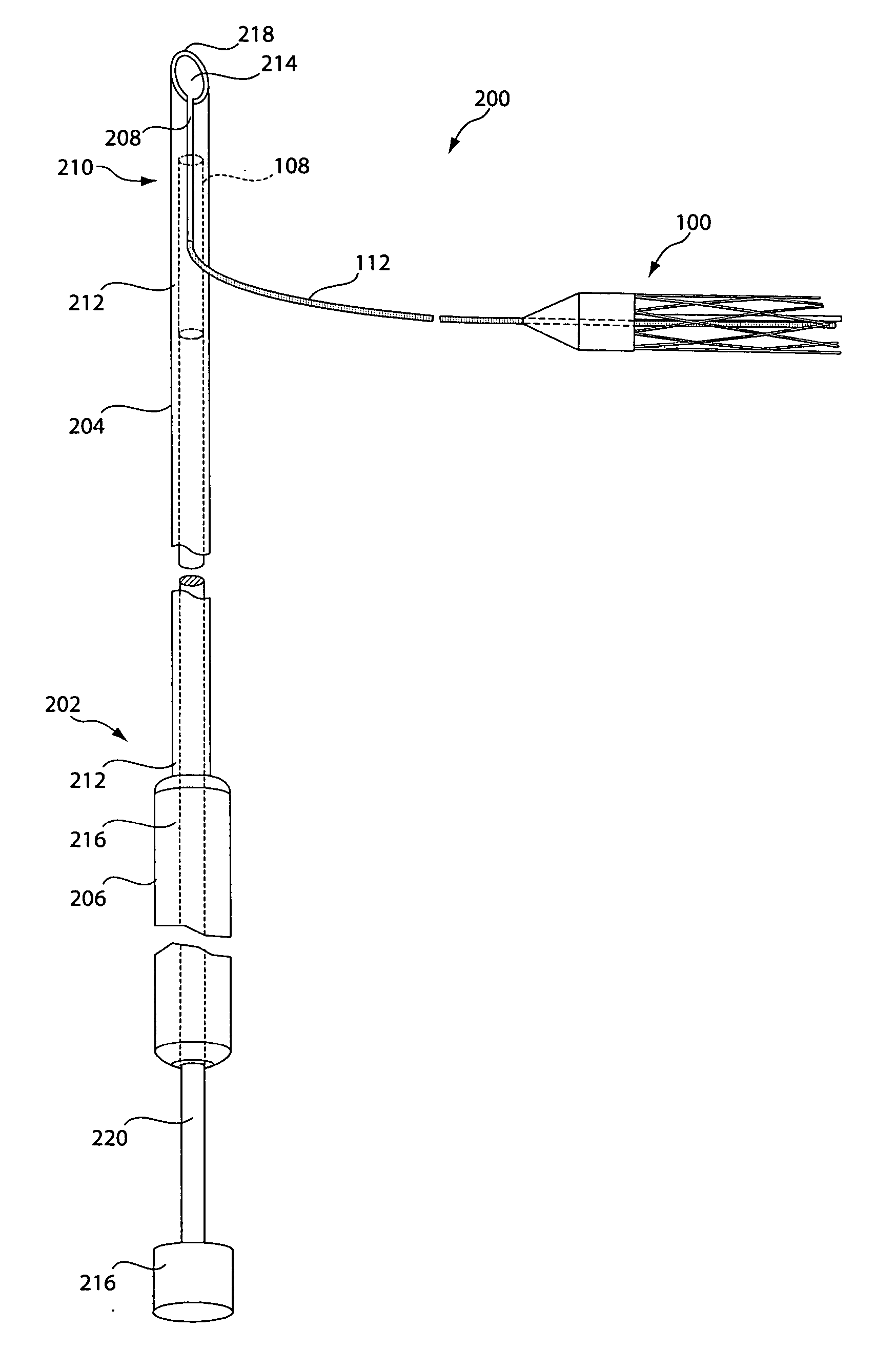
[0031] As described in summary above, in various illustrative embodiments, the invention is directed to a sling assembly including a supportive and implantable sling having tubular configuration in which filaments may be operator actuated to transition the sling from an elongated width-contracted state to a shorter width-expanded state. In other illustrative embodiments, the invention is directed to delivery devices for delivering the sling of the invention, anchors for anchoring the sling in place, various association members for associating the sling assembly of the invention with a suitable delivery device, and kits including a delivery device and sling assembly of the invention.

[0032]FIG. 1A depicts a sling assembly 100 in an untensioned state according to an illustrative embodiment of the invention. As shown, the sling assembly 100 includes: a tubular and implantable sling 102; two dilators 104 and 106 located at either end 102a and 102b, respectively, of the sling 102; two an...


PUM


Abstract

The invention generally relates to surgically implantable supportive slings. More specifically, in various embodiments, the invention is directed to systems, devices and methods relating to a surgically implantable supportive sling having an adjustable shape.

Description

FIELD OF THE INVENTION [0001] The invention generally relates to surgically implantable supportive slings. More specifically, in various embodiments, the invention is directed to systems, devices and methods relating to a surgically implantable shape adjustable supportive sling. BACKGROUND [0002] Urinary incontinence affects over 13 million men and women of all ages in the United States. Stress urinary incontinence (SUI) affects primarily women and is generally caused by two conditions, intrinsic sphincter deficiency (ISD) and hypermobility. These conditions may occur independently or in combination. In ISD, the urinary sphincter valve, located within the urethra, fails to close properly (coapt), causing urine to leak out of the urethra during stressful activity. Hypermobility is a condition in which the pelvic floor is distended, weakened, or damaged, causing the bladder neck and proximal urethra to rotate and descend in response to increases in intra-abdominal pressure (e.g., due ...

Claims


Application Information

Patent Timeline
Patent Type & Authority Applications(United States)
IPC IPC(8): A61F2/00
CPCA61B17/0482A61B17/0483A61B2017/00805A61F2/0045A61B2017/0417A61B2017/0496A61B2017/06052A61B2017/0409
Inventor CHU, MICHAEL S. H.
Owner BOSTON SCI SCIMED INC
Learn More