Display device
- Summary
- Abstract
- Description
- Claims
- Application Information
AI Technical Summary
Benefits of technology
Problems solved by technology
Method used
Image
Examples
embodiment 1
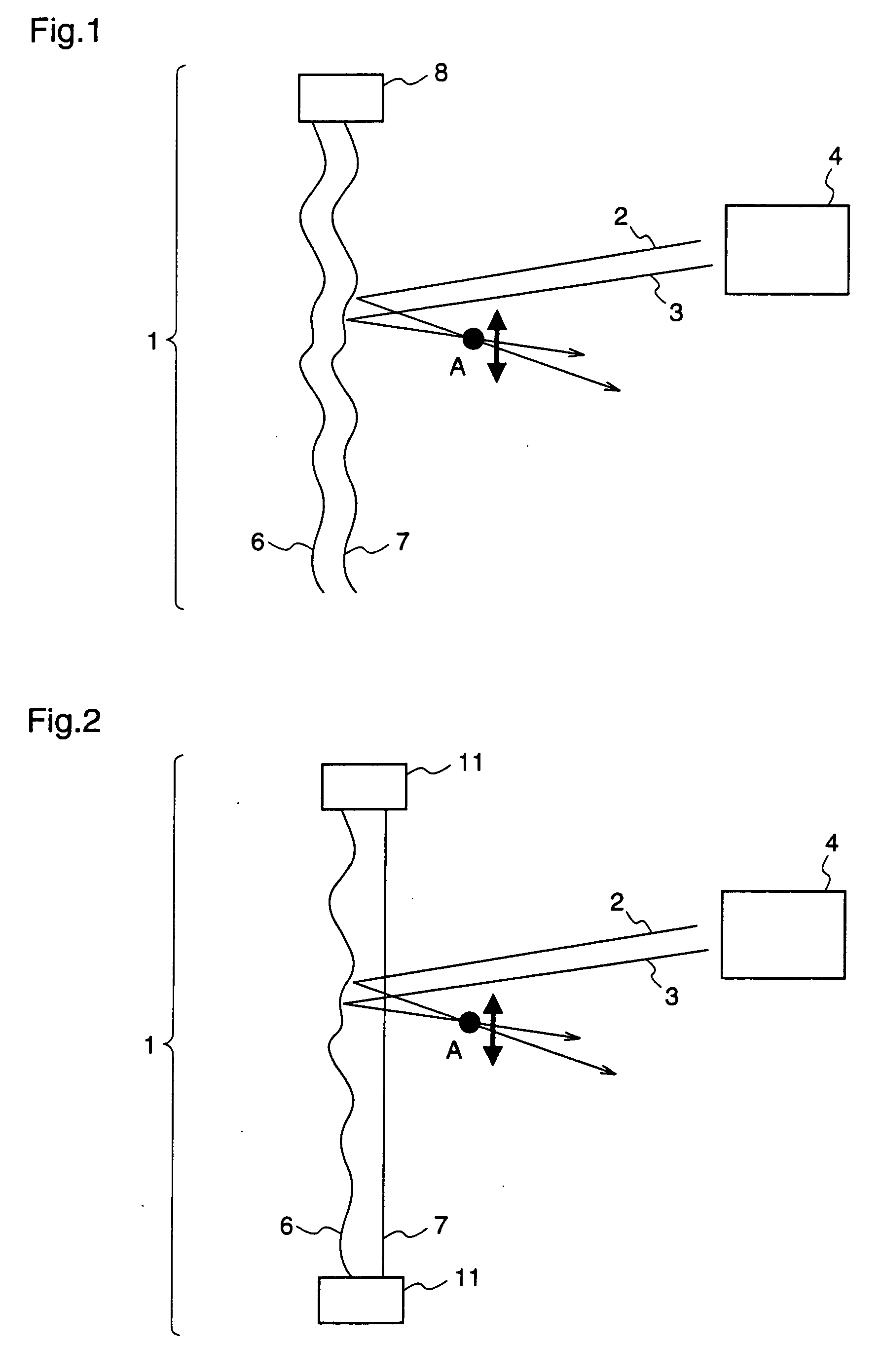
[0027]FIG. 1 is a lateral view of a display device according to a first embodiment of the present invention. As shown in FIG. 1, the display device relating to the first embodiment comprises an image receiving part 1, a light source 4, and a blower unit 8. Further, the image receiving part 1 comprises two screens 6 and 7. Any material may be used for the screens 6 and 7 so long as it can reflect coherent light. For example, it may be a material used for a screen of a general overhead projector (OHP).
[0028] Light beams 2 and 3 emitted from the light source 4 are projected on the image receiving part 1. The projected laser beams are reflected at the screen 6 or 7 to be displayed as an image. In this first embodiment, it is assumed that the laser beams are reflected at the screen 7. When the screen 7 is transparent, the laser beams may be reflected at the screen 6. As a material of the transparent screen, for example, transparent vinyl or transparent film may be employed. The blower u...
embodiment 2
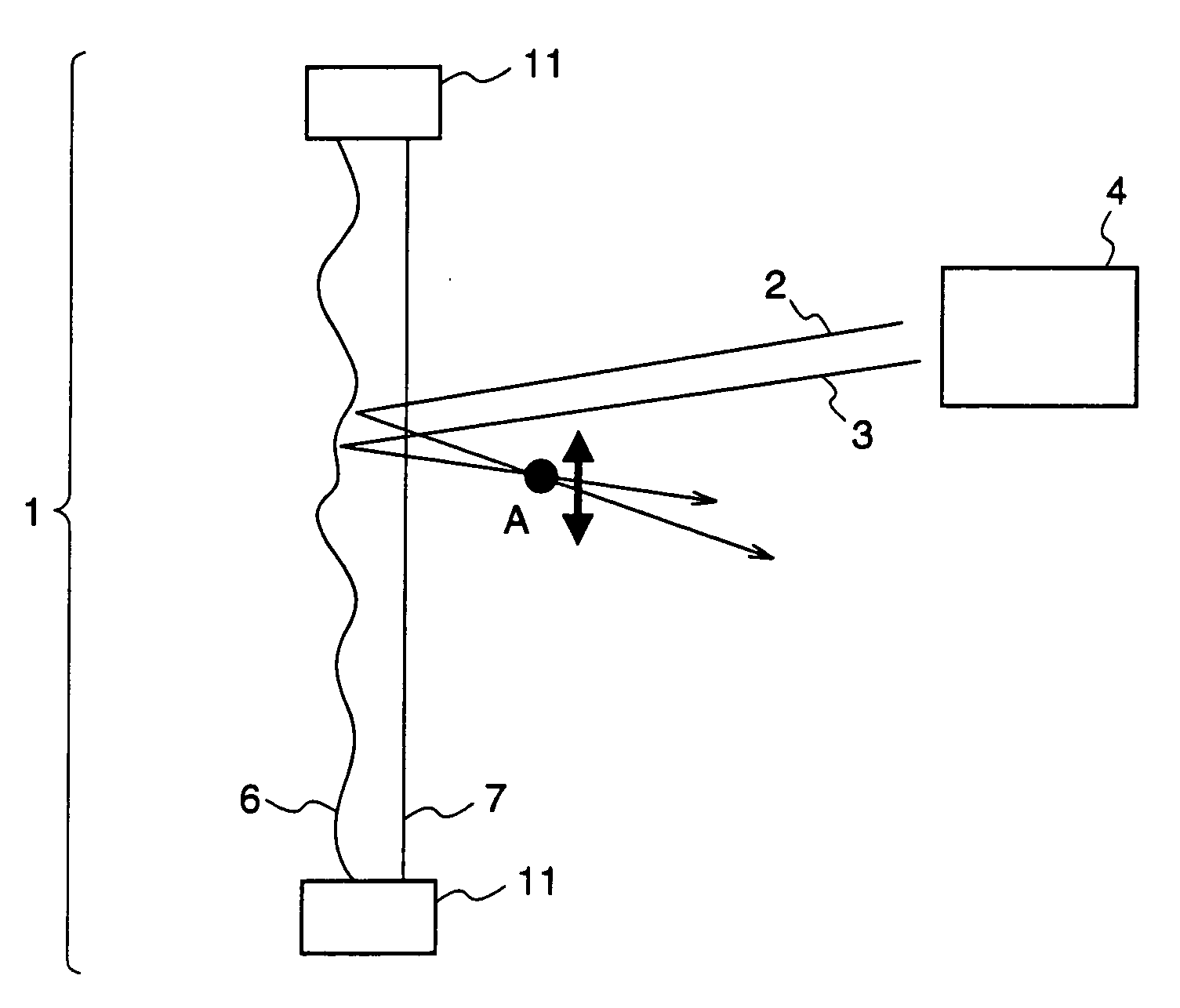
[0033]FIG. 2 is a lateral view of a display device according to a second embodiment of the present invention. The same constituents as those shown in FIG. 1 are given the same reference numerals. In the display device relating to the second embodiment of the invention, an image receiving part which comprises two or more screens, at least one of the screens being vibrated, functions as a speaker.
[0034] Hereinafter, a description will be given of the case where the image receiving part 1 comprises two screens. With reference to FIG. 2, the image receiving part 1 of the display device comprises two screens 6 and 7. The circumferences of the screens 6 and 7 are sealed with a shielding part 11. A gas is filled in a space between the screen 6 and the screen 7. Further, it is possible to vibrate the screen 6 or 7 by supplying, from a portion of the shielding part 11, something (e.g., an audio signal) that activates the gas between the screen 6 and screen 7. In the display device according...
embodiment 3
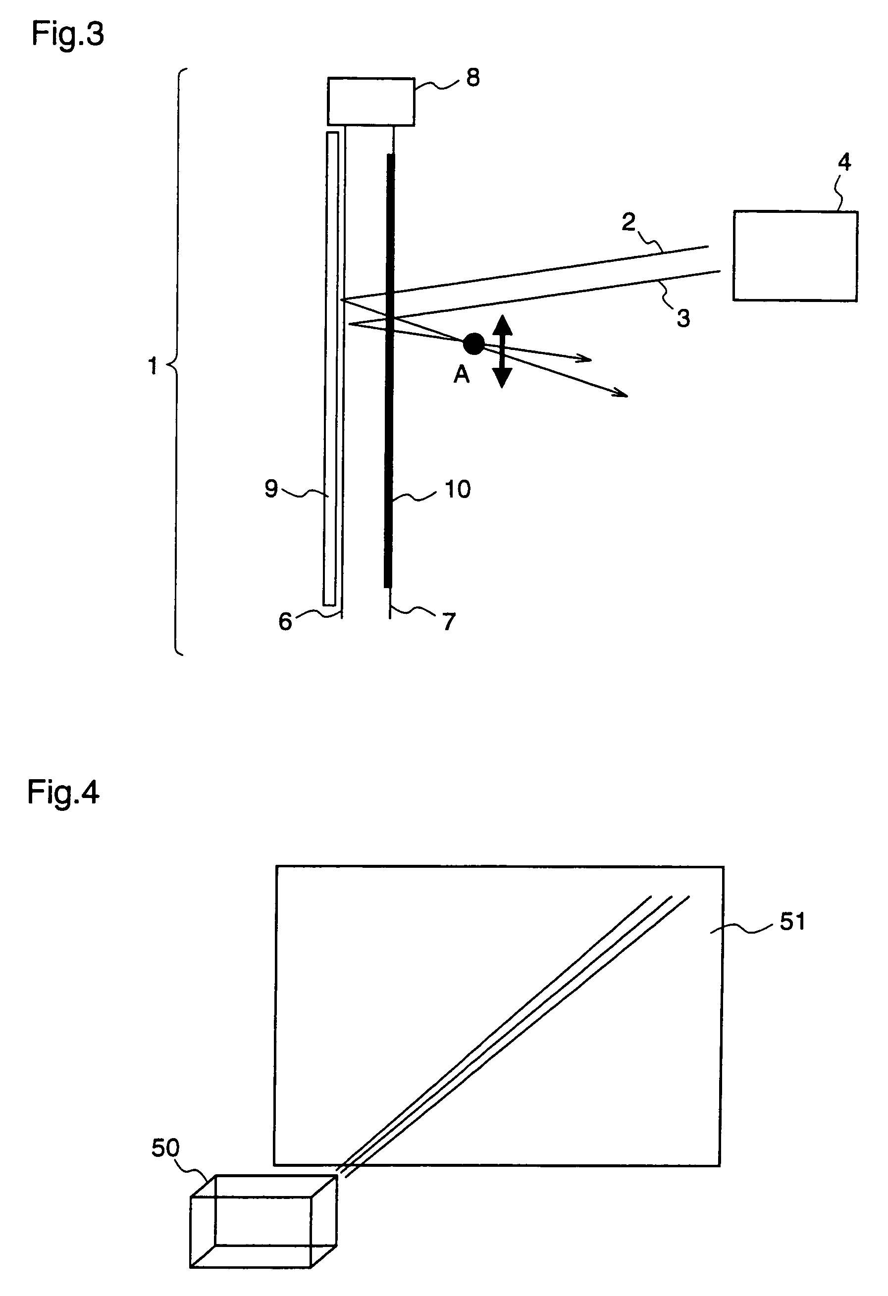
[0038]FIG. 3 is a lateral view of a display device according to a third embodiment of the present invention. The same constituents as those shown in FIG. 1 are given the same reference numerals. In the display device relating to the third embodiment of the invention, an image receiving part 1 is composed of two or more screens, and a coil is provided on at least one of the screens while a metal film as a magnetic body is provided on at least one of the remaining films.
[0039] Hereinafter, a description will be given of the case where the image receiving part 1 comprises two screens. With reference to FIG. 3, in the display device according to the third embodiment of the present invention, the image receiving part 1 is composed of screens 6 and 7, and a coil 9 is provided on the screen 6 while a metal film 10 is provided on the screen 7, as means for vibrating the screens. The metal film 10 comprises Fe as a magnetic material. When current is randomly supplied to the coil 9, an elect...
PUM
 Abstract
Description
Claims
Application Information
 - R&D
- Intellectual Property
- Life Sciences
- Materials
- Tech Scout
- Unparalleled Data Quality
- Higher Quality Content
- 60% Fewer Hallucinations
Browse by: Latest US Patents, China's latest patents, Technical Efficacy Thesaurus, Application Domain, Technology Topic, Popular Technical Reports.
© 2025 PatSnap. All rights reserved.Legal|Privacy policy|Modern Slavery Act Transparency Statement|Sitemap|About US| Contact US: help@patsnap.com


