Eureka AIR delivers breakthrough ideas for toughest innovation challenges, trusted by R&D personnel around the world.

Unmanned monitoring system and monitoring method using omni-directional camera

a monitoring system and camera technology, applied in the field of unmanned monitoring systems and monitoring methods using omni-directional cameras, can solve the problems of low resolution, degradation of monitoring performance, inefficient monitoring systems in view of power consumption and software, etc., and achieve the effect of increasing the processing speed of images

Inactive Publication Date: 2007-02-15
SAMSUNG ELECTRONICS CO LTD
View PDF8 Cites 30 Cited by
  • Summary
  • Abstract
  • Description
  • Claims
  • Application Information

AI Technical Summary

Benefits of technology

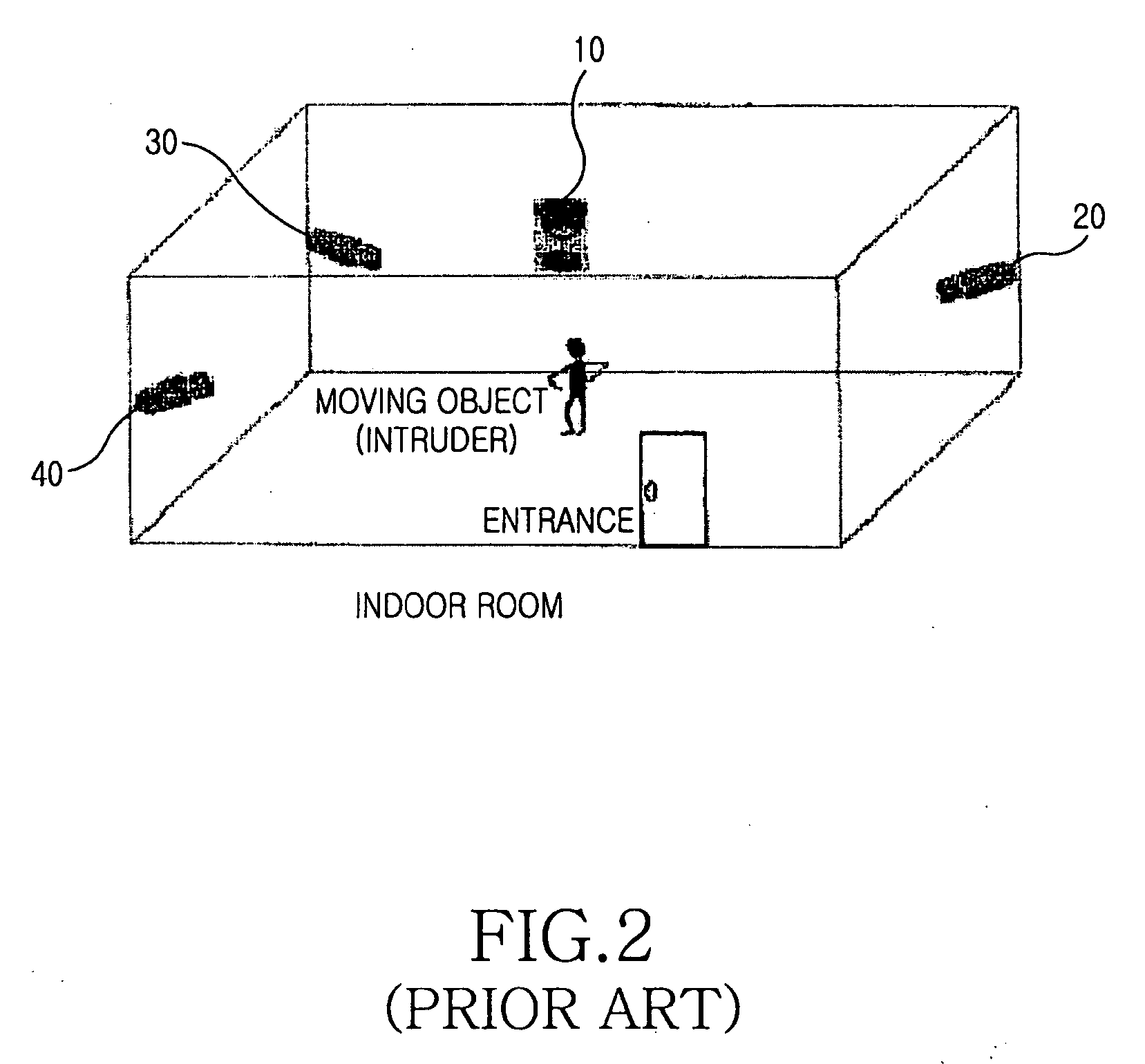
[0012] Another object of the present invention is to provide an unmanned monitoring system and a monitoring method capable of detecting and tracing the direction of a moving object using an omni-directional camera while increasing a speed for processing an image by optimizing the detecting procedure for the moving object.

Problems solved by technology

In order to convert the circular image into the linear panoramic image, coordinate conversion of the image must be performed several times. The coordinate conversion requires high precision, and a relatively long processing time to compensate for parts not having pixels when producing the linear panoramic image, which causes low resolution and degradation of monitoring performance.
Thus, the monitoring system is inefficient in view of power consumption and software when it is installed in equipment having a low storage capacity, such as a robot.
The conventional panoramic visual surveillance system requires relatively long software processing time when it is applied to a large monitoring region, causes low resolution and degradation of performance.
The conventional monitoring system equipped with one omni-directional camera and a plurality of active cameras is inefficient for automatically detecting and tracing a moving object or an intruder in a predetermined region.

Method used


Image

  • Unmanned monitoring system and monitoring method using omni-directional camera
  • Unmanned monitoring system and monitoring method using omni-directional camera
  • Unmanned monitoring system and monitoring method using omni-directional camera

Examples


Embodiment Construction

[0024] Hereinafter, embodiments of the present invention will be described with reference to the accompanying drawings. In the following detailed description, a detailed description of known functions and configurations incorporated herein will be omitted when it may make the subject matter of the present invention rather unclear.

[0025] The present invention provides a system and a method for performing 360° unmanned monitoring work within equipment having a low storage capacity, such as a robot, by using only one omni-directional camera. The present invention detects the movement of an object from an image obtained by the omni-directional camera installed in equipment having a low storage capacity. The present invention traces the moving object, samples a region where the movement of the object occurs (hereinafter, referred to as a movement region), rotates the image into a frontal image while compensating for the inclination of the image in such a manner that the user can easily ...


PUM


Abstract

Disclosed are an unmanned monitoring system and a monitoring method for performing 360° unmanned monitoring work in equipment having a low storage capacity, such as a robot, by using one omni-directional camera. When an image is input through the omni-directional camera, a movement of an object is detected from the image. Then, the movement region is sampled by tracing the object and the image for the movement region is rotated into a frontal image while compensating for inclination of the image in order to allow a user to easily view the image. Thus, the frontal image is transmitted to a mobile communication terminal of a user, such as a mobile phone or a PDA.

Description

PRIORITY [0001] This application claims the benefit under 35 U.S.C. 119(a) of an application entitled “Unmanned Monitoring System And Monitoring Method Using Omni-Directional Camera” filed with the Korean Intellectual Property Office on Aug. 9, 2005 and assigned Serial No. 2005-72872, the contents of which are incorporated herein by reference. BACKGROUND OF THE INVENTION [0002] 1. Field of the Invention [0003] The present invention relates to an unmanned monitoring system and a monitoring method using an omni-directional camera. More particularly, the present invention relates to an unmanned monitoring system and a monitoring method for performing 360° unmanned monitoring work using one omni-directional camera. [0004] 2. Description of the Related Art [0005] As modern society has rapidly developed and become more complex, there is a need to protect and monitor human and / or technology resources. In this regard, a security and monitoring system plays an important role. Performance of ...

Claims


Application Information

Patent Timeline
IPC IPC(8): H04N7/00H04N7/18
CPCG06T7/20H04N5/23238G06K9/00771G08B13/19628G08B13/19663G06V20/52H04N23/698H04N7/18
Inventor KO, BYOUNG-CHULKIM, KWANG-CHOON
Owner SAMSUNG ELECTRONICS CO LTD
Why Eureka
Eureka Blog
Learn More