
Single camera system and method for range and lateral position measurement of a preceding vehicle

a single camera and vehicle technology, applied in scene recognition, instruments, and reradiation, etc., can solve the problems of low cost of laser radar, less effective in adverse weather conditions, and high cost of millimeter wave radar systems such as 77 ghz systems

Inactive Publication Date: 2007-02-15
VISTEON GLOBAL TECH INC
View PDF26 Cites 22 Cited by
  • Summary
  • Abstract
  • Description
  • Claims
  • Application Information

AI Technical Summary

Benefits of technology

The present invention provides a system for determining the range and lateral position of a vehicle using a camera, sonar sensor, and processor. The camera generates an electrical image of a region of interest containing a preceding vehicle, while the sonar sensor views a second region of interest. The processor evaluates the characteristics of the electrical image and sonar data to identify the vehicle and determine its range and lateral position. The system can also use an edge enhanced algorithm to simplify the image and evaluate objects constructed from multiple segments. The technical effects of the invention include improved accuracy in identifying the vehicle and its position, as well as improved reliability in adverse weather conditions.

Problems solved by technology

However, millimeter wave type radar systems such as 77 Ghz systems are typically quite expensive.
Laser radar is low cost but has the drawback of requiring moving parts which scan the laser across a field of view.
Furthermore, the laser is less effective in adverse weather conditions which may effect the reflectivity of the preceding vehicle.
Finally, radar generally is not well suited to identify the object and give an accurate lateral position.
However, these systems are typically difficult to manufacture due to the accurate alignment required between the two stereo cameras and requires two image processors.
In view of the above, it can be seen that conventional ACC systems typically do not have a high cost-performance ratio even though they may perform to the desired functional requirements.

Method used


Image

  • Single camera system and method for range and lateral position measurement of a preceding vehicle
  • Single camera system and method for range and lateral position measurement of a preceding vehicle
  • Single camera system and method for range and lateral position measurement of a preceding vehicle

Examples


Embodiment Construction

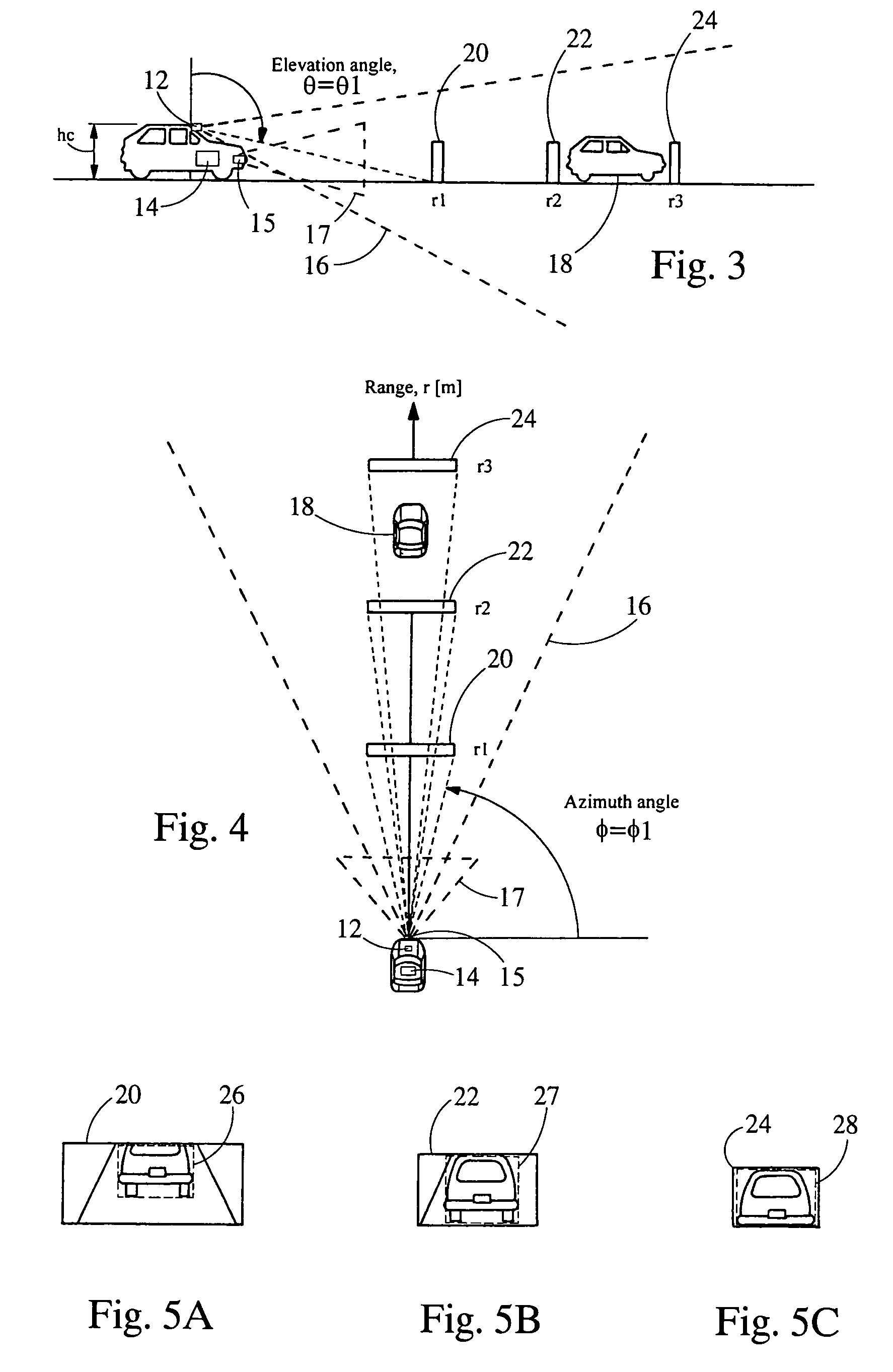
[0025] Referring now to FIG. 1, a system embodying the principles of the present invention is illustrated therein and designated at 10. As its primary components, the system 10 includes a camera 12, a sonar sensor 15 and a processor 14. The camera 12 is located in the rearview mirror to collect an optical image of a first region of interest 16 including a vehicle 18. The sonar sensor 15 is located near the front bumper of the vehicle to collect data of a second region of interest 17. Typically, the first and second regions of interest 16, 17 partially overlap.

[0026] The optical image received by the camera 12, is converted to an electrical image that is provided to the processor 14. To filter out unwanted distractions in the electronic image and aid in determining the range of the vehicle 18, the processor 14 calculates the position of multiple windows 20, 22, 24 within the first region of interest 16. The windows 20, 22, 24 are located at varying target ranges from the camera 12. ...


PUM


Abstract

A system for determining range and lateral position of a vehicle is provided. The system includes a camera, a sonar and a processor. The camera is configured to view a long range region of interest and generate an electrical image of the region. The sonar is configured to view a short range region of interest an output a sonar signal. The processor is in electrical communication with the camera and the sonar to receive the electrical image and the sonar signal. The processor analyzes the image and the sonar signal in order to determine the range of an object.

Description

BACKGROUND [0001] 1. Field of the Invention [0002] The present invention generally relates to a system and method for range and lateral position measurement of a preceding vehicle. [0003] 2. Description of Related Art [0004] Radar and stereo camera systems for adaptive cruise control (ACC), have been already introduced into the market. Recently, radar has been applied to for pre-crash safety systems and collision avoidance. Typically, the range and lateral position measurement of a preceding vehicle is accomplished utilizing radar and / or stereo camera systems. Radar systems can provide a very accurate range. However, millimeter wave type radar systems such as 77 Ghz systems are typically quite expensive. Laser radar is low cost but has the drawback of requiring moving parts which scan the laser across a field of view. Furthermore, the laser is less effective in adverse weather conditions which may effect the reflectivity of the preceding vehicle. For example, if mud covers the refle...

Claims


Application Information

Patent Timeline
Patent Type & Authority Applications(United States)
IPC IPC(8): B60Q1/00
CPCG01S11/12G01S15/025G06K9/00805G06T7/004G08G1/16G01S15/931G08G1/166G06T7/70G01S15/86G06V20/58
Inventor MIYAHARA, SHUNJI
Owner VISTEON GLOBAL TECH INC
Learn More