
Ink-Jet Recording Apparatus

a recording device and inkjet technology, applied in the direction of typewriters, printing devices, printing, etc., can solve the problems of increasing the production cost of the ink-jet recording device, affecting the efficiency of printing, and affecting the quality of printing, so as to prevent the occurrence of jamming of the sheet, prevent the unsatisfactory running of the ink, and prevent the effect of jamming

Inactive Publication Date: 2007-02-08
BROTHER KOGYO KK
View PDF1 Cites 26 Cited by
  • Summary
  • Abstract
  • Description
  • Claims
  • Application Information

AI Technical Summary

Benefits of technology

[0008] However, generally, the separating means that separates the two upstream-side rollers from each other when the recording sheet is fed in the upstream direction, needs to have a complicated arrangement, which leads to increasing the production cost of the ink-jet recording device.
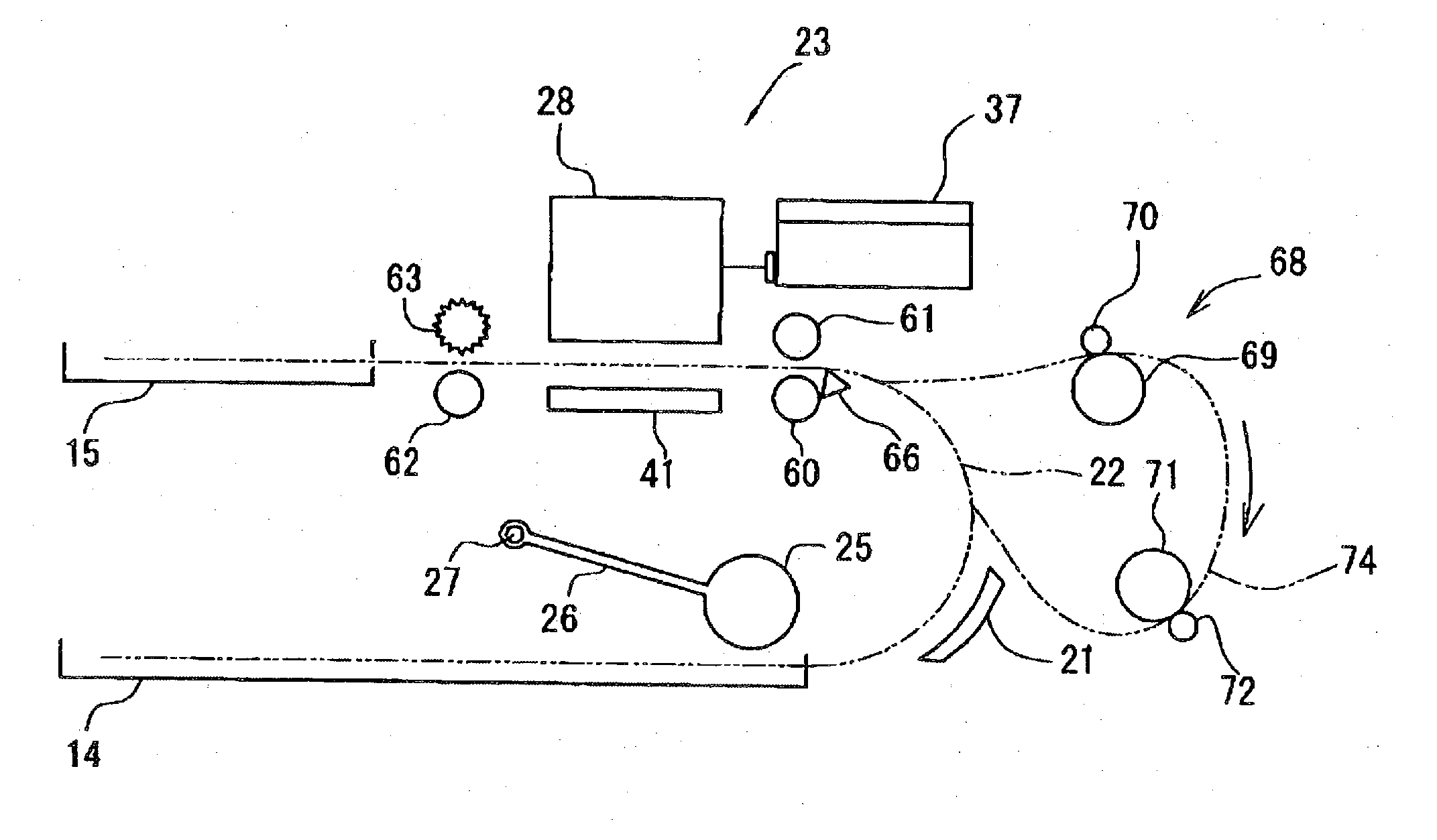
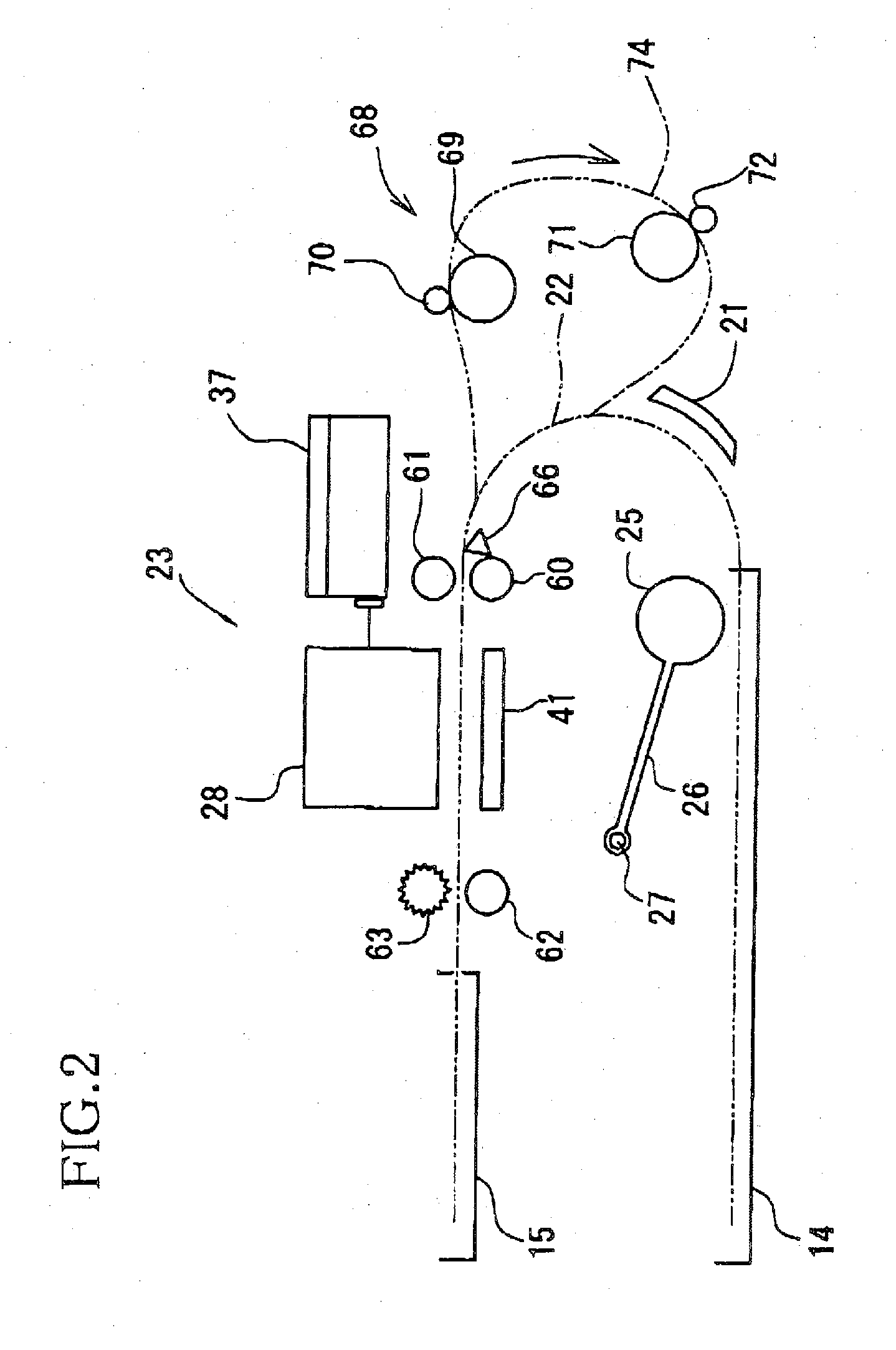
[0010] It is therefore an object of the present invention to solve at least one of the above-indicated problems. It is another object of the present invention to provide an ink-jet recording apparatus that can quickly record an image with a high: quality on each of opposite surfaces of a recording sheet, while effectively preventing occurrence of jamming of the recording sheet.
[0014] It is generally known that after droplets of ink are ejected onto a recording sheet, a cockling phenomenon that the recording sheet deforms and ripples occurs as the ink droplets dry up. However, in the present ink-jet recording apparatus, the trailing end of the recording sheet enters the jamming prevention range within the first pre-determined time duration. Therefore, after the trailing end of the recording sheet enters the jamming prevention range, the drying-up of the ink droplets and the occurrence of the cockling phenomenon ends or completes. Thus, when the recording sheet is fed upstream to the nip position, the trailing end of the sheet is normally nipped by the two upstream-side rollers, without causing jamming of the sheet. Since the ink droplets have dried up when the trailing end of the recording sheet is nipped by the two rollers, undesirable running of the ink can be prevented.
[0015] According to the present invention, the trailing end of the recording sheet can be positioned in the specific range in which the occurrence of jamming of the sheet is prevented, before the cockling phenomenon as one of the major causes of the jamming occurs. Therefore, even in double-side and no-margin printing modes in which an image is recorded on each of opposite surfaces of a recording sheet up to a trailing end of the each surface, the occurrence of jamming of the sheet can be effectively prevented. In addition, since the occurrence of jamming is prevented by controlling the feeding of the recording sheet, the construction of the ink-jet recording apparatus need not be complicated or the production cost of the same need not be increased.

Problems solved by technology

However, generally, the separating means that separates the two upstream-side rollers from each other when the recording sheet is fed in the upstream direction, needs to have a complicated arrangement, which leads to increasing the production cost of the ink-jet recording device.
And, if the trailing-end portion of the recording sheet to which the cockling phenomenon has occurred is introduced into the space left between the two upstream-side rollers, then the trailing-end portion of the sheet may not be nipped by the two rollers, i.e., jamming of the sheet may occur.

Method used


Image

  • Ink-Jet Recording Apparatus
  • Ink-Jet Recording Apparatus
  • Ink-Jet Recording Apparatus

Examples


Embodiment Construction

[0024] Hereinafter, there will be described a preferred embodiment of the present invention by reference to the drawings.

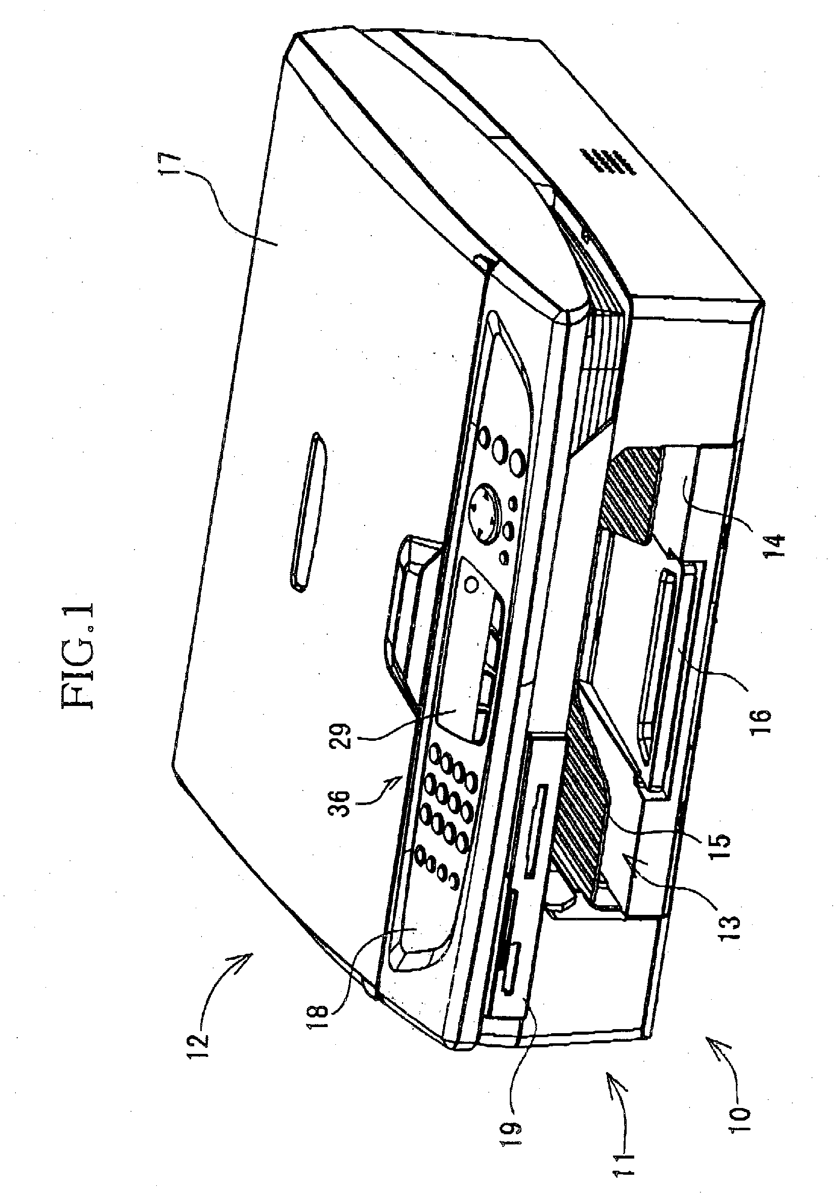
[0025]FIG. 1 shows a multi-function device (MFD) 10 to which the present invention is applied. The MFD 10 includes, in a lower portion thereof, a printer portion 11 and a communication portion, not shown, and additionally includes, in an upper portion thereof, a scanner portion 12. The MFD 10 has a printer function, a scanner function, a copier function, and a facsimile-machine function. In the present embodiment, the printer portion 11 is constituted by an ink-jet recording apparatus. Thus, the MFD 10 enjoys a small size. However, the MFD 10 may employ a plurality of sheet-supply cassettes and / or an automatic document feeder (ADF). The MFD 10 can be connected to a personal computer (PC) 38 (FIG. 4), and can record, based on image data (e.g., document data) sent from the PC 38, images (e.g., documents) on recording sheets. The MFD 10 may be connected to a digital...


PUM


Abstract

An inkjet recording apparatus including an ink-jet recording head; two upstream-side rollers which feed a recording sheet to the head in a downstream direction along a sheet-feed path; two downstream-side rollers which feed the sheet from the head; at least one rotating device which rotates, in a forward direction corresponding to the downward direction, the upstream-side and downstream-side rollers, and rotates, in a backward direction corresponding to an upstream direction opposite to the downward direction, at least the downstream-side rollers; a sheet reversing device which reverses the sheet and feeds the reversed sheet to the upstream-side rollers; and a control device which controls, when the head records an image on one surface of the sheet, the rotating device to rotate, in the forward direction, the upstream-side and downstream-side rollers such that a trailing end of the sheet is fed to a position outside a radius range between (a) a nip position where the upstream-side rollers nip the sheet and (b) a downstream-side position distant from the nip position in the downstream direction by a distance equal to a radius of one of the upstream-side rollers that is located on one side of the sheet-feed path on which the recording head is provided, and which subsequently controls the rotating device to rotate, in the backward direction, the downstream-side rollers to feed the sheet in the upstream direction along the sheet-feed path so that the trailing end of the sheet enters the radius range within a first predetermined time duration.

Description

[0001] The present application is based on Japanese Patent Application No. 2005-226356 filed on Aug. 4, 2005, the contents of which are incorporated herein by reference. BACKGROUND OF THE INVENTION [0002] 1. Field of the Invention [0003] The present invention relates to an ink-jet recording apparatus, and particularly to such an ink-jet recording apparatus that can record an image on each of opposite sides or surfaces of a recording sheet. [0004] 2. Discussion of Related Art [0005] There is known an ink-jet recording device including a sheet feeder that feeds a recording sheet; and an ink-jet recording head that ejects droplets of ink toward the recording sheet, so as to record a desirable image on the recording sheet. The sheet feeder includes a pair of upstream-side rollers that are provided on an upstream side of the recording head along a sheet-feed path and that nip the recording sheet and, when the upstream-side rollers are rotated in a forward direction, the recording sheet i...

Claims


Application Information

Patent Timeline
Patent Type & Authority Applications(United States)
IPC IPC(8): B41J29/38
CPCB41J3/60B41J11/0065
Inventor IZUCHI, MASATOSHI
Owner BROTHER KOGYO KK
Learn More