
Charge/discharge control circuit for audio device

a control circuit and audio device technology, applied in the direction of instruments, pulse techniques, recording signal processing, etc., to achieve the effect of suppressing audible artifacts

Active Publication Date: 2007-02-08
ANALOG DEVICES INC
View PDF12 Cites 19 Cited by
  • Summary
  • Abstract
  • Description
  • Claims
  • Application Information

AI Technical Summary

Benefits of technology

[0006] It is a further object of this invention to provide such an improved charge / discharge control circuit which reduces unwanted audible artifacts yet provides fast charging and discharging of the a.c. coupling capacitors.
[0007] It is a further object of this invention to provide such an improved charge / discharge control circuit which greatly reduces or eliminates the need for external clamping circuits.
[0012] It is a further object of this invention to provide such an improved charge / discharge control circuit which is relatively low in power consumption.
[0014] The invention results from the realization that an improved charge / discharge control circuit for controlling current through an input / output audio device which reduces unwanted artifacts yet provides fast charging and discharging of the a.c. coupling capacitors can be effected with a waveform generation circuit responsive to first and second voltage references for generating a multistage voltage waveform profile which is approximately an inaudible current waveform for suppressing audible artifacts in the input / output device.
[0016] This invention features a charge / discharge control circuit for controlling current through an input / output audio device including a first voltage reference and a second voltage reference. A waveform generation circuit responsive to the first and second voltage references generates a multi-stage waveform profile which is approximately an inaudible waveform for suppressing audible artifacts in the input / output device.
[0018] This invention also features a charge / discharge control circuit for controlling current through an input / output audio device including a second voltage reference, a waveform generation circuit responsive to the first and second voltage references for generating a multi-stage waveform profile which is approximately an integral of an inaudible waveform for suppressing audible artifacts in the input / output device.

Problems solved by technology

In electronic devices that interface with audio devices through an a.c. coupling capacitance, a change in the DC state on either side of the a.c. coupling capacitor due to power-up, power-down or some other voltage transition can result in an audible artifact due to charging / discharging of the a.c. coupling capacitor, which causes current to flow through the a.c. coupling capacitor and the audio dev

Method used


Image

  • Charge/discharge control circuit for audio device
  • Charge/discharge control circuit for audio device
  • Charge/discharge control circuit for audio device

Examples


Embodiment Construction

[0035] Aside from the preferred embodiment or embodiments disclosed below, this invention is capable of other embodiments and of being practiced or being carried out in various ways. Thus, it is to be understood that the invention is not limited in its application to the details of construction and the arrangements of components set forth in the following description or illustrated in the drawings. If only one embodiment is described herein, the claims hereof are not to be limited to that embodiment. Moreover, the claims hereof are not to be read restrictively unless there is clear and convincing evidence manifesting a certain exclusion, restriction, or disclaimer.

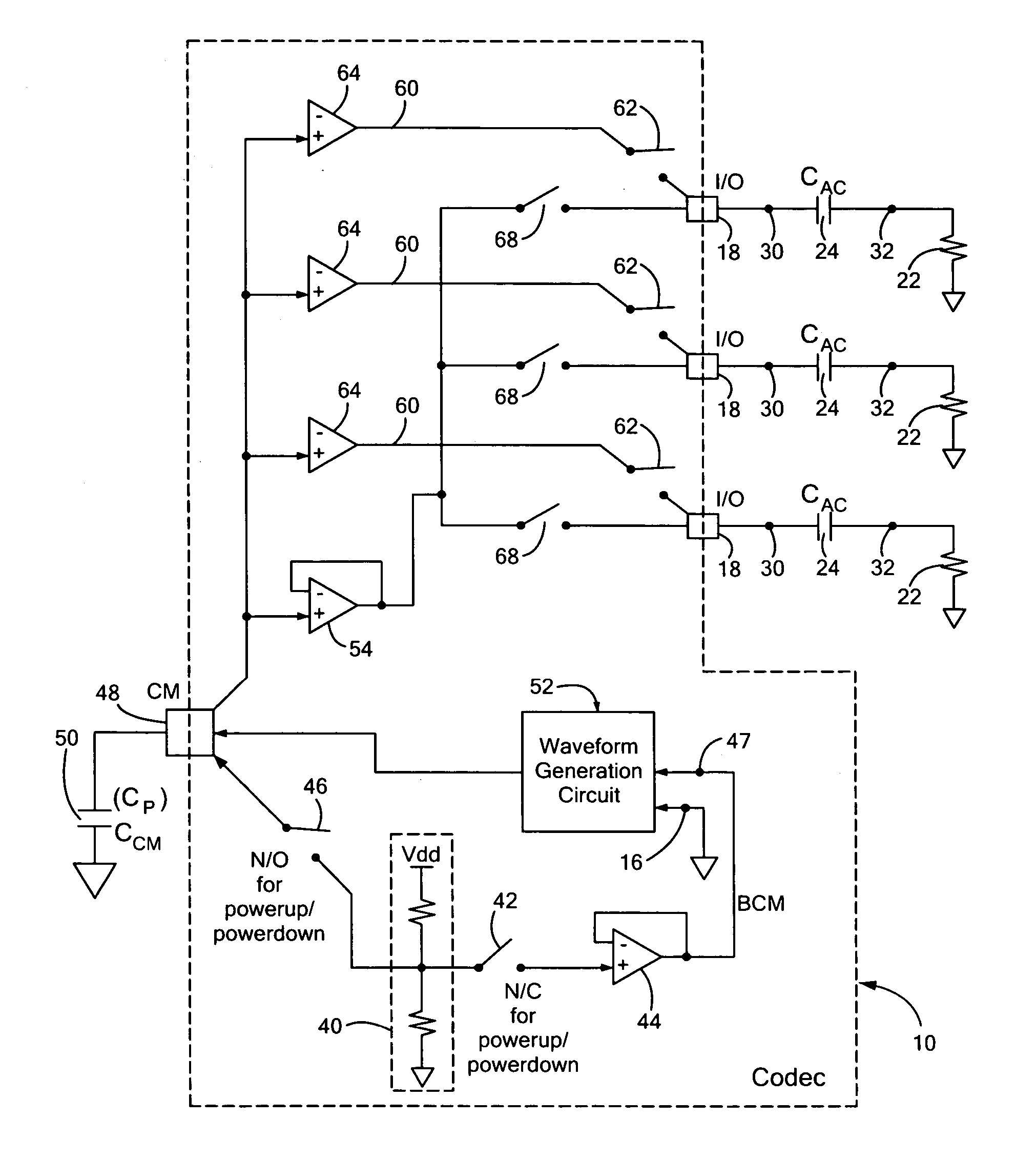
[0036] There is shown in FIG. 1 a codec 10 according to this invention installed on a PC board 12. Codec 10 is provided with two voltages, e.g. positive power supply vdd at terminal 14 and negative power supply GND at terminal 16. Codec 10 also has a contact 48 for signal conditioning of the common mode voltage by common ...


PUM


Abstract

A charge / discharge control circuit for controlling current through an input / output audio device includes a first voltage reference; a second voltage reference and a waveform generation circuit responsive to the first and second voltage references for generating a multi-stage waveform profile which is approximately an inaudible waveform for suppressing audible artifacts in the input / output device.

Description

RELATED APPLICATIONS [0001] This application claims benefit of U.S. Provisional Application Ser. No. 60 / 695,101 filed Jun. 29, 2005, herein incorporated by this reference.FIELD OF THE INVENTION [0002] This invention relates to a charge / discharge control circuit for controlling current through an input / output audio device and more particularly to a dewhumper a / k / a de-whumper. BACKGROUND OF THE INVENTION [0003] In electronic devices that interface with audio devices through an a.c. coupling capacitance, a change in the DC state on either side of the a.c. coupling capacitor due to power-up, power-down or some other voltage transition can result in an audible artifact due to charging / discharging of the a.c. coupling capacitor, which causes current to flow through the a.c. coupling capacitor and the audio device. For example, codec systems are used to drive input and output devices, e.g. speakers, headphones, amplifiers, microphones, CD players. The I / O contacts of the codec generally co...

Claims


Application Information

Patent Timeline
IPC IPC(8): H03K5/01
CPCG11B20/10527G11B20/22G11B20/24H03M1/0881G11B2020/10555H03F1/305H03G3/348G11B2020/10546
Inventor MCHUGH, COLIN B.JOSEFSSON, OLAFUR MAR
Owner ANALOG DEVICES INC
Learn More