
Method of generating surface defined by boundary of three-dimensional point cloud

a point cloud and boundary technology, applied in the field of generating a three-dimensional (3d) surface, can solve the problems of increasing the frame rate generally places a practical limitation on and the complexity of the surface that can be rendered within a given frame rate increases accordingly. , to achieve the effect of more efficient approaches to rendering

Active Publication Date: 2007-02-01
NVIDIA CORP
View PDF5 Cites 144 Cited by
  • Summary
  • Abstract
  • Description
  • Claims
  • Application Information

AI Technical Summary

Benefits of technology

[0012] Recognizing the need for more efficient approaches to rendering complex 3D surfaces, embodiments of the present invention provide a method of generating a 3D surface defined by a boundary of a 3D point cloud. In vario

Problems solved by technology

Generating complex 3D surfaces is among the more computationally expensive tasks performed by contemporary virtual display systems such as personal computers (PCs) and gaming consoles.
Unfortunately, the frame rate generally places a practical limitation on the complexity of surfaces that can be rendered.
However, as the efficiency of rendering algorithms increases, the complexity of surfaces that can be rendered within a given frame rate increases accordingly.
The Marching Cubes technique has at least two problems when it comes to generating surfaces in a real-time display environment.
The first problem is that it marches through the cubes in a view independent manner.
Because many of the cubes may not actually be visible to a viewer in the display environment, compute cycles are unnecessary wasted by marching through the non-visible cubes.
The second problem with the Marching Cubes technique is that it marches through a 3D dataset, even though the 3D surface produced thereby is generally rendered in 2D.
This also adds unnecessary computational cost to generating the 3D surface.
Unfortunately, the performance of screen space approaches such as ray tracing and point splatting tend to be even slower than that of the Marching Cubes technique.
One reason is because these screen space approaches fail to make use of specialized graphics acceleration hardware such as the triangle rendering pipeline included in most contemporary virtual display systems.

Method used


Image

  • Method of generating surface defined by boundary of three-dimensional point cloud
  • Method of generating surface defined by boundary of three-dimensional point cloud
  • Method of generating surface defined by boundary of three-dimensional point cloud

Examples


Embodiment Construction

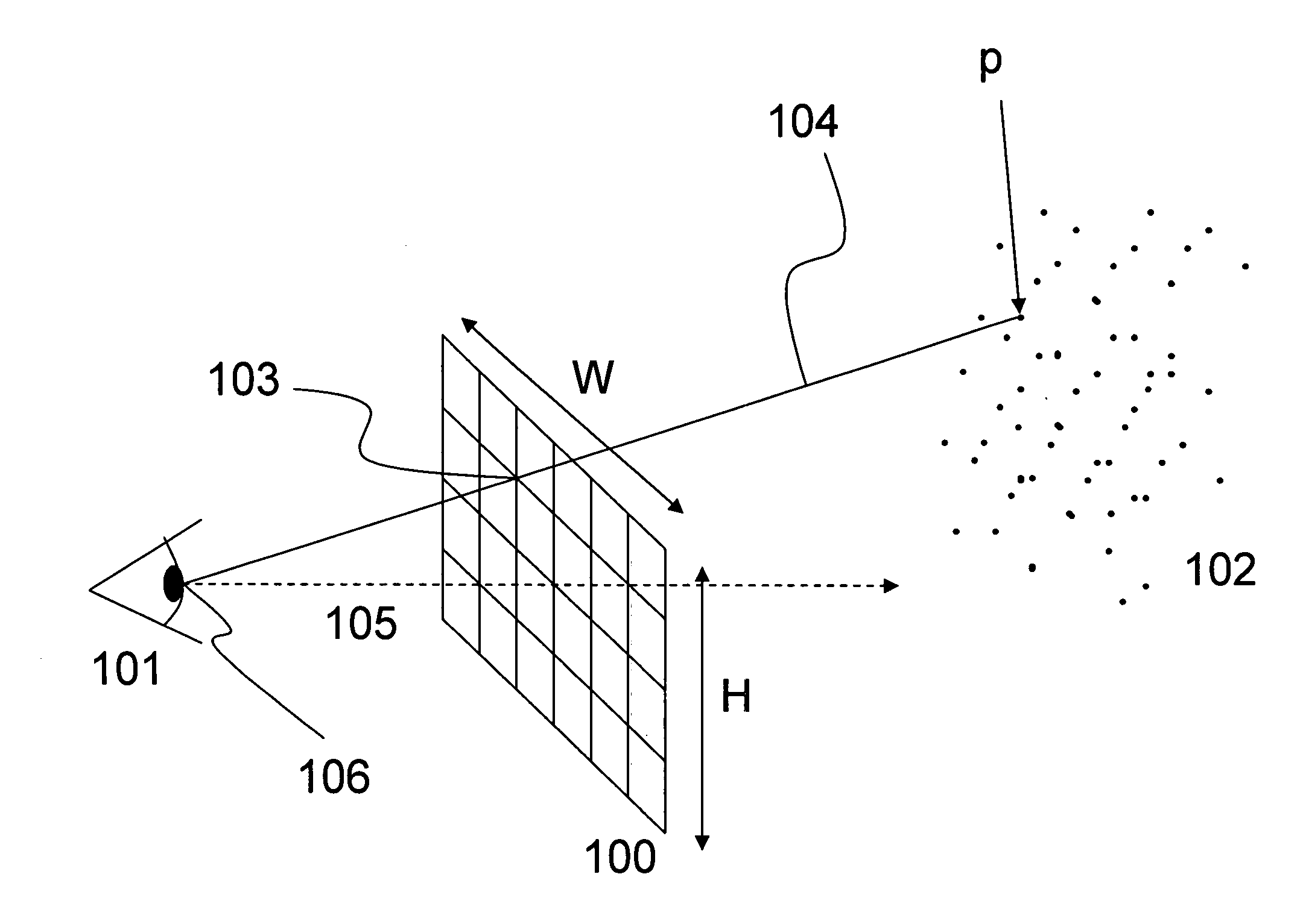
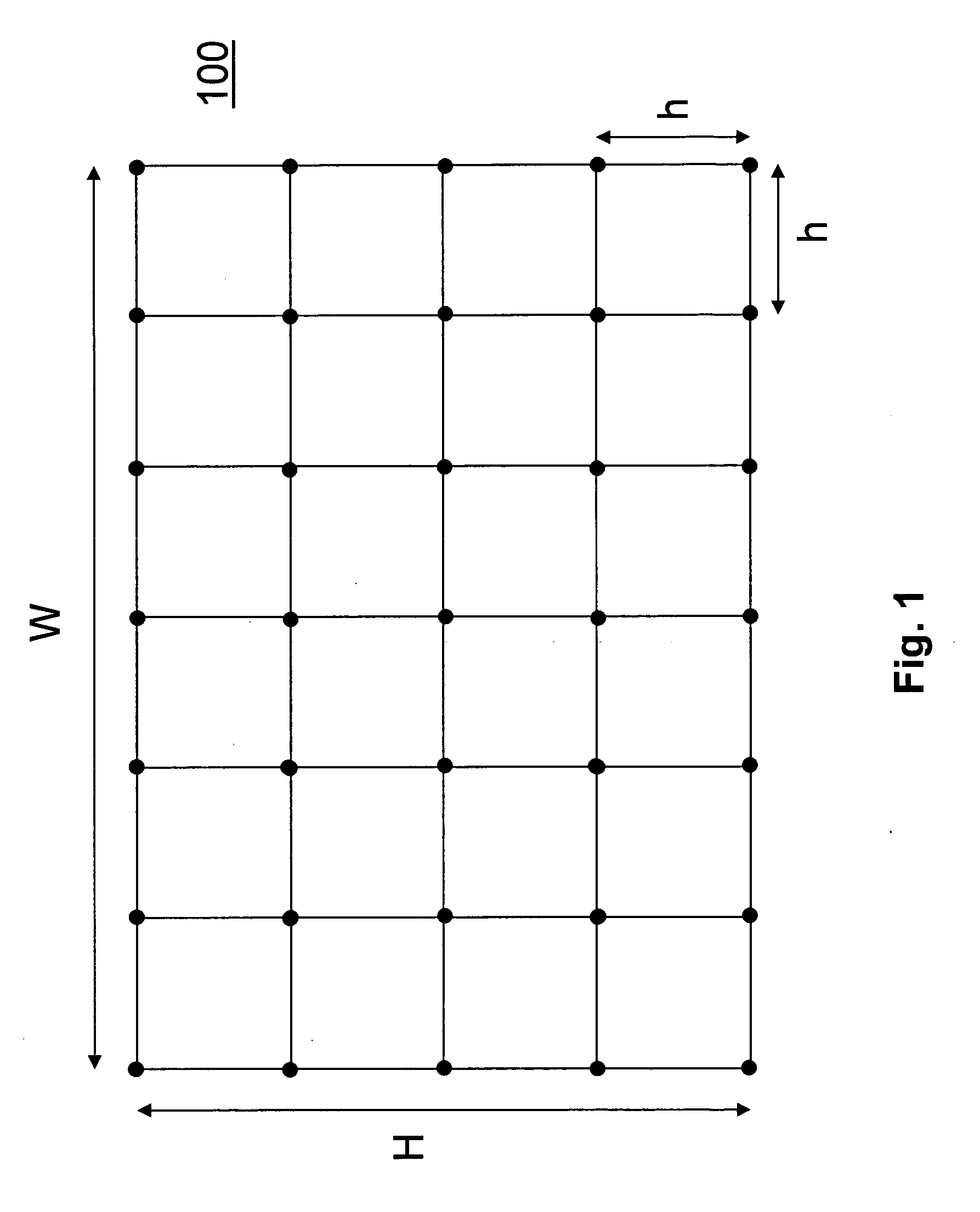
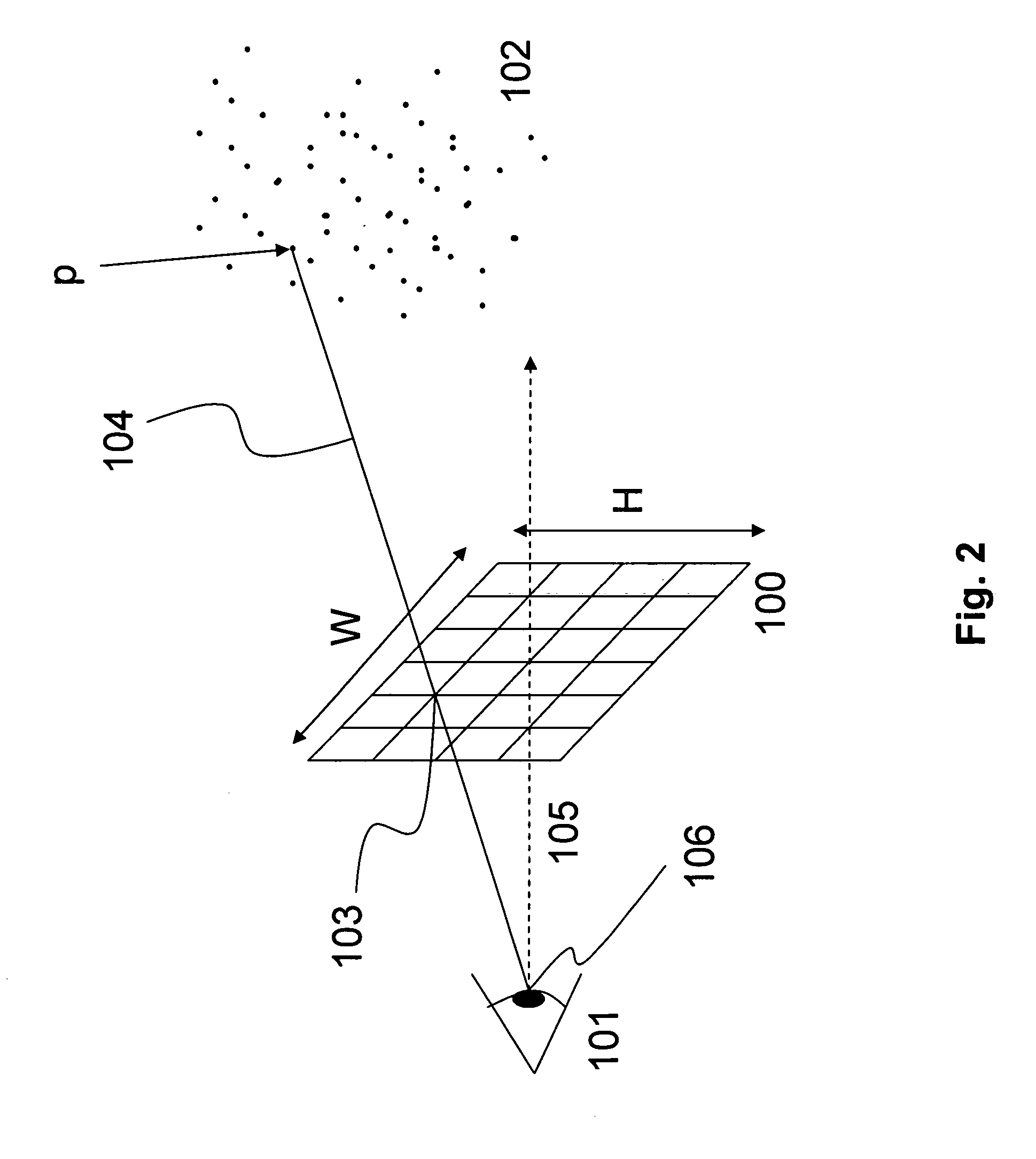
[0031] Embodiments of the invention provide a method of generating a three-dimensional (3D) surface defined by the boundary of a 3D point cloud. According to the method, a depth map and a density map are formed from the 3D point cloud. The depth and density maps are then used to form a two-dimensional (2D) mesh representing the 3D surface by defining connectivity between points in the 3D point cloud. The 2D mesh is transformed into a 3D mesh defining 3D graphics primitives, which are then rendered in a virtual display system.

[0032] The term “3D point cloud” used herein denotes any plurality of three dimensionally related points, e.g., a finite set of 3D points. Each point in the 3D point cloud may be generally represented by a vector [x, y, z]T in Cartesian space or a vector [x, y, z, 1]T in homogeneous coordinates.

[0033] The term “virtual display system” used herein refers to any combination of hardware and / or software capable of rendering a 3D surface. For example, the virtual d...


PUM


Abstract

Disclosed is a method of generating a three-dimensional (3D) surface defined by a boundary of a 3D point cloud. The method comprises generating density and depth maps from the 3D point cloud, constructing a 2D mesh from the depth and density maps, transforming the 2D mesh into a 3D mesh, and rendering 3D polygons defined by the 3D mesh.

Description

BACKGROUND OF THE INVENTION [0001] 1. Field of the Invention [0002] The present invention relates generally to a method of generating a three-dimensional (3D) surface for a virtual display system. More particularly, the invention relates to a method of generating a 3D surface defined by a boundary of a 3D point cloud. [0003] 2. Description of the Related Art [0004] Generating complex 3D surfaces is among the more computationally expensive tasks performed by contemporary virtual display systems such as personal computers (PCs) and gaming consoles. For example, a complex 3D surface may be composed of millions of tiny shapes that must be individually rendered in order to generate the surface, and rendering each of the shapes generally requires performing a large number of mathematical operations such as geometric transformations, coordinate transformations, viewing and clipping transformations, lighting, shading, and hidden surface removal, to name but a few. Because of the high comput...

Claims


Application Information

Patent Timeline
IPC IPC(8): G06T15/20
CPCG06T17/20G06T7/0051G06T7/50
Inventor MULLER-FISCHER, MATTHIAS HEINZSCHIRM, SIMON DAVIDDUTHALER, STEFAN FELIX
Owner NVIDIA CORP
Learn More