
Pen like optical mouse

a mouse and pen-like technology, applied in the field of optical mouse, can solve the problems of reducing the contrast of images, enlarge the diameter of the mouse, and difficult to hold the mouse in one's hand,

Inactive Publication Date: 2007-02-01
FOXLINK IMAGE TECH
View PDF6 Cites 10 Cited by
  • Summary
  • Abstract
  • Description
  • Claims
  • Application Information

AI Technical Summary

Benefits of technology

[0009] An object of the present invention is to provide pen like optical mouse in which light emitted from a light emitting e

Problems solved by technology

Therefore, the arrangement of the optical motion sensor in such manner results in enlargement of the diameter of the mouse.
It is difficult to use the mouse while holding in one's hand.
Thus, some ligh

Method used


Image

  • Pen like optical mouse
  • Pen like optical mouse

Examples


Embodiment Construction

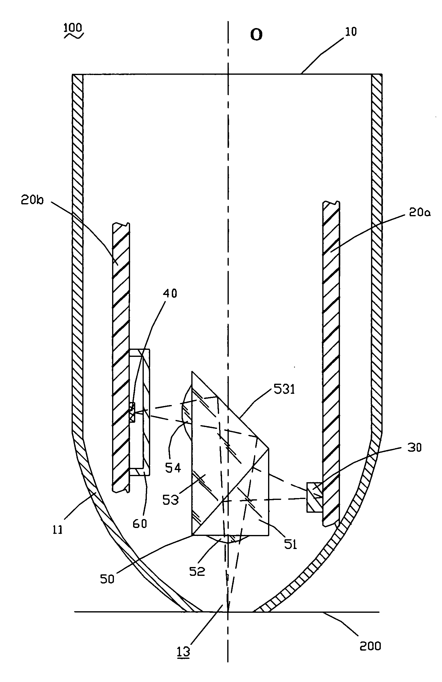
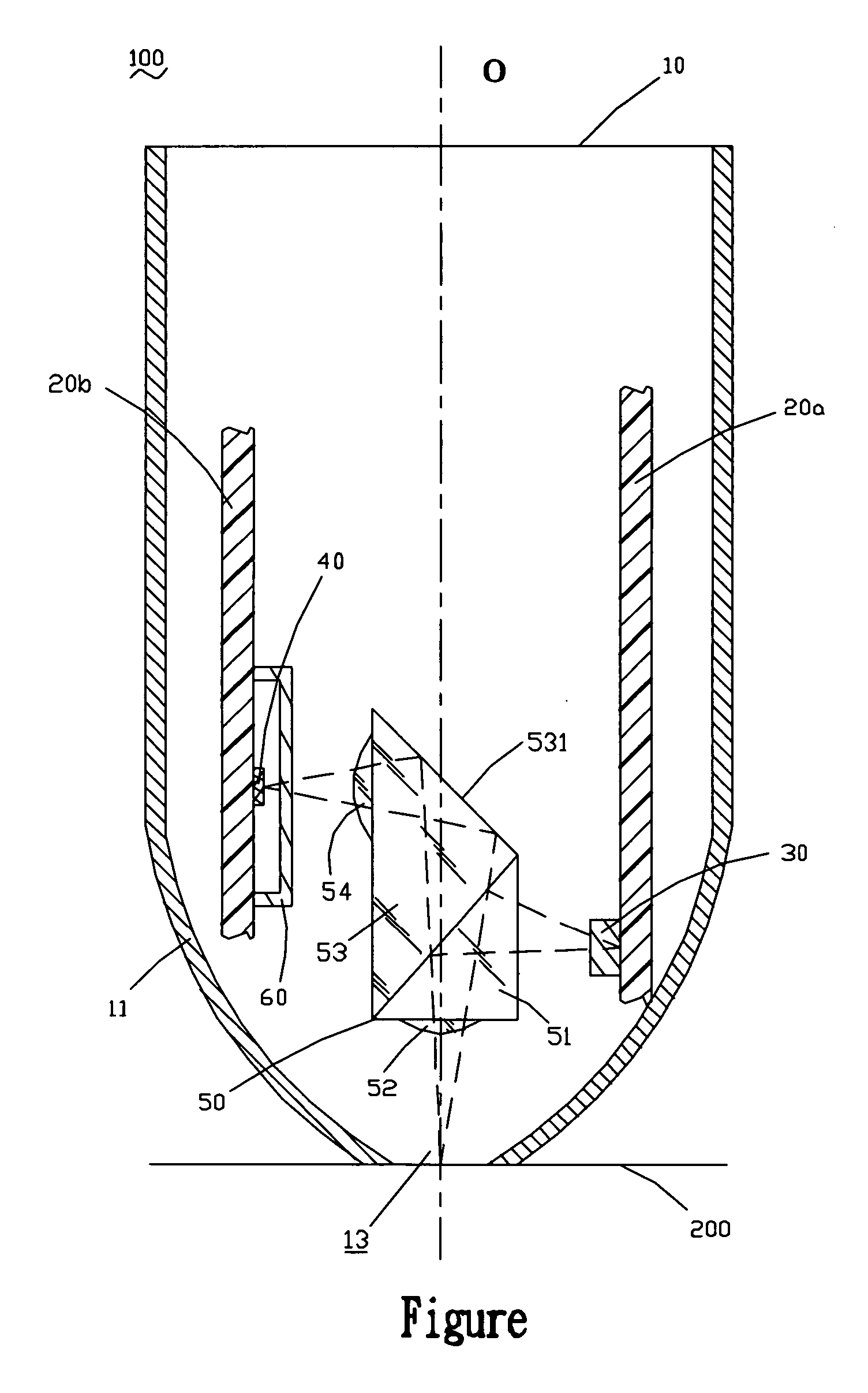
[0021] Referring to the FIGURE, a pen like optical mouse 100 in accordance with the present invention includes a pen like mouse main body 10, a first printed circuit board 20a, a second printed circuit board 20b, a light emitting element 30, a sensor die 40, an imaging system 50, and an aperture 60.

[0022] The main body 10 of the optical mouse 100 is shaped like a pen with a tapered pen head 11 at a lower end thereof such that a user can conveniently grasp it and perform natural writing operation. An opening 13 is defined in the bottom of the pen head 11. The main body 10 has a central axis O.

[0023] The first printed circuit board 20a is disposed on a side of the interior of the main body 10 and in a direction parallel to the central axis O of the main body 10.

[0024] The light emitting element 30 is mechanically mounted on the first printed circuit board 20a and electrically connected to the first printed circuit board 20a. The light emitting element 30 is activated to emit light ...


PUM


Abstract

A pen like optical mouse includes a pen like mouse main body, a printed circuit board disposed in the main body in a direction parallel to a central axis of the main body, a light emitting element mounted on the first printed circuit board, a sensor die mounted on the second printed circuit board, and an imaging system for guiding light emitted from the light emitting element to be irradiated onto and reflected by a work surface and then guiding the reflected light so as to be imaged and incident on the sensor die. As the light emitting element and the sensor die are arranged on two separate printed circuit boards, light emitted from the light emitting element is prevented from being directly incident on the senor die so as not to reduce the contrast of images.

Description

BACKGROUND OF THE INVENTION [0001] 1. Field of the Invention [0002] The present invention relates to an optical mouse, and more particularly, to a pen like optical mouse in which light emitted from a light emitting element is prevented from being directly incident on a sensor die, thus ensuring the performance of the pen like optical mouse by not reducing the contrast of images. [0003] 2. The Related Art [0004] A mouse, which is one of the input means for computers, is a device that is used to directly or indirectly instruct a computer on the coordinates of a cursor displayed on a monitor of a computer. Such mice are classified into two types; ball mice that each inputs the moving direction and distance of the mouse by utilizing the rotation of a ball, and optical mice that each detects the moving direction and distance of the mouse by tracing the movement of the images of a work surface formed by light emitted from the mouse body. [0005] As need not to be periodically cleaned and h...

Claims


Application Information

Patent Timeline
IPC IPC(8): G09G5/08
CPCG06F3/03545G06F3/0317
Inventor CHANG, KUO-WENTSAO, MING-SEN
Owner FOXLINK IMAGE TECH
Learn More