Method of producing a foamed part and foaming tool for applying such method

a foaming tool and foaming technology, applied in the field of foaming parts production, can solve the problems of increasing costs, and achieve the effect of reducing production effort and being easy to manufactur

Inactive Publication Date: 2007-02-01
ARVINMERITOR GMBH
View PDF1 Cites 31 Cited by
  • Summary
  • Abstract
  • Description
  • Claims
  • Application Information

AI Technical Summary

Benefits of technology

[0018] The foaming tool according to the invention for applying this method has a tool bottom part, a tool upper part and a foaming chamber between the tool bottom part and the tool upper part. The tool bottom part and the tool upper part have a cutting edge and a supporting surface that are located at an edge of the foaming chamber. The cutting edge and supporting surface are essentially superimposed in an opening direction, and are closely moved past each other during opening in order to trim an edge of the foamed part. Due to the positioning of the cutting edge relative to the supporting surface, in particular relative to an outer edge of the supporting surface, an outer skin is sheared off during opening of the foaming tool. The outer skin that is sheared off is in fact the outer skin that was previously placed in the foaming chamber, i.e. in a cavity between the tool bottom part and the tool upper part, and was provided with a foamed backing. In this process, a straight cutting rim on the outer skin will be created. Trimming of the car body attachment part after foaming in a separate work step is thus eliminated to provide reduced production effort, and to provide a car body attachment part that is cost-efficient and easy to manufacture.

Problems solved by technology

The trimming of the car body attachment part is done in a separate work step, which increases cost.

Method used


Image

  • Method of producing a foamed part and foaming tool for applying such method
  • Method of producing a foamed part and foaming tool for applying such method
  • Method of producing a foamed part and foaming tool for applying such method

Examples


Embodiment Construction

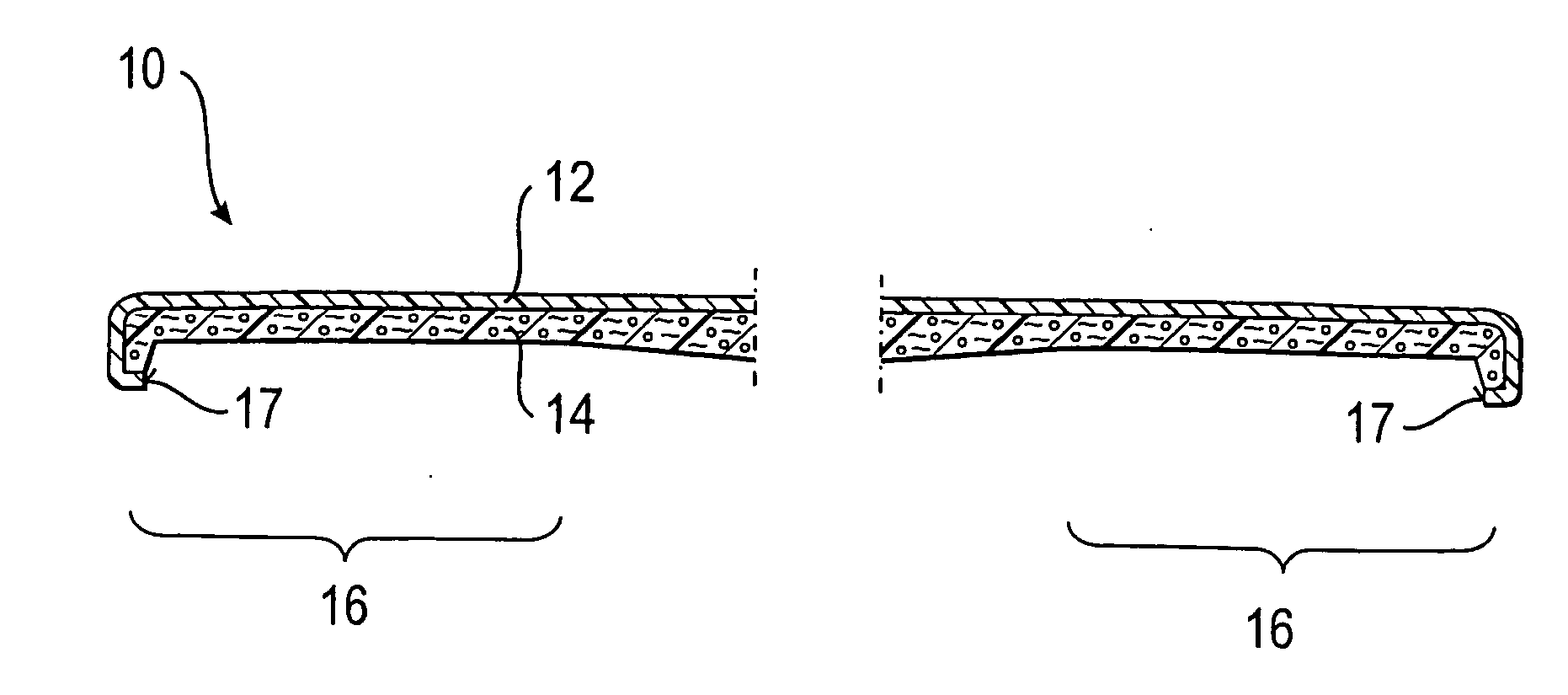
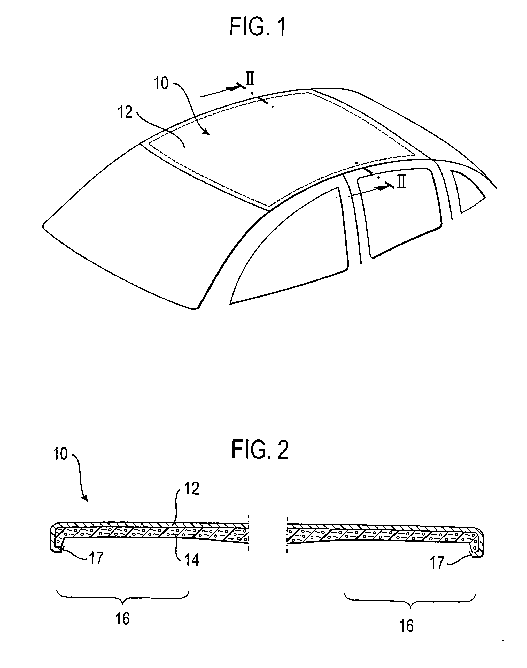
[0028]FIG. 1 shows a foamed part, to be more precise a car body attachment part, in the form of a roof module 10. The car body attachment part, however, could also be configured as a fender, door or flap (engine hood, trunk lid) of a motor vehicle. A lining part for a vehicle interior space could also be produced by the following method.

[0029] When mounted to the vehicle, the roof module 10 has a visible outside which is formed by a thin, deep-drawn foil outer skin (outer skin 12). The outer skin 12 is made of plastic or aluminum and preferably is dyed throughout and coated, respectively, to replace an outside painting.

[0030] Directly adjoining the backside of the outer skin 12 there is a plastic layer 14 that is constituted by a fiber-reinforced PU foam, and which is formed by providing the outer skin 12 with a foamed or injection-molded backing, with the glass fibers being introduced in the foam by the LFI method to reinforce the plastic layer 14 (FIG. 2).

[0031] The plastic lay...


PUM

PropertyMeasurementUnit
thicknessaaaaaaaaaa
thicknessaaaaaaaaaa

Abstract

A method of producing a foamed part, in particular a car body attachment part for a motor vehicle, includes the following steps. A foaming tool is provided that includes a tool bottom part and a tool upper part. An outer skin is placed in the tool bottom part and an expandable material is applied. The foaming tool is closed, with at least one portion of the outer skin being located in a gap between the tool bottom part and the tool upper part. After the foaming process, during opening of the foaming tool, the outer skin is trimmed by the foaming tool itself. The invention further relates to a foaming tool for applying such a method.

Description

RELATED APPLICATIONS [0001] The application claims priority to European Patent Application No. 05 016 405.2 which was filed on 28 Jul. 2005. BACKGROUND OF THE INVENTION [0002] The invention relates to a method of producing a foamed part, in particular a car body attachment part for a motor vehicle, and further to a foaming tool for applying such method. [0003] Car body attachment parts for a motor vehicle are parts that are attached to a vehicle body. These parts define at least portions of an outer skin of a vehicle in the readily mounted state, and are visible from outside of the vehicle. Car body attachment parts may be flaps (doors, lids), bumpers, or roof modules, for example. Roof modules having a sliding roof unit would also comprise a car body attachment part. [0004] Foamed car body attachment parts, in particular roof modules, comprising a glass-fiber reinforced polyurethane (PU) material are already known, with glass fibers being injected in plastic using a so-called long ...

Claims


Application Information

Patent Timeline
Patent Type & Authority Applications(United States)
IPC IPC(8): B29C44/12
CPCB26F1/386B62D29/002B29C44/1257B26F2210/06
Inventor LUDWIG, MATTHIASBECK, HERBERTBATKE, HARALDNIEBUHR, FRANKLANGHOFF, HANS-JOACHIMHARDEL, SVENNIESNER, TOBIAS
Owner ARVINMERITOR GMBH
Why Eureka
Try Eureka